Radiation structure and array antenna

A radiation structure and array antenna technology, applied in the field of microstrip antenna units, array antennas, and radiation structures, can solve the problems of high profile, complex assembly, and increase of array antenna parts, and can reduce Q value, reduce electromagnetic coupling, improve The effect of isolation

Active Publication Date: 2019-08-06
COMBA TELECOM TECH (GUANGZHOU) CO LTD
View PDF8 Cites 11 Cited by
  • Summary
  • Abstract
  • Description
  • Claims
  • Application Information

AI Technical Summary

Problems solved by technology

In order to solve the mutual coupling effect, that is, the isolation between the antenna ports, or to solve the problem of working bandwidth, the main measure of the microstrip antenna is to adopt a double-layer patch scheme, that is, the radiation piece is added with a parasitic patch, and each layer of patch is passed through a plastic card. The components are interconnected and fastened to the reflector, or the patches of each layer are printed on the multi-layer PCB, which leads to the increase of array antenna parts and complicated assembly while obtaining the corresponding performance of the existing microstrip antenna. , Section heightening and other issues

Method used


Image

  • Radiation structure and array antenna
  • Radiation structure and array antenna
  • Radiation structure and array antenna

Examples


Embodiment Construction

[0037] Embodiments of the present invention are described in detail below, examples of which are shown in the drawings, wherein the same or similar reference numerals designate the same or similar elements or elements having the same or similar functions throughout. The embodiments described below by referring to the figures are exemplary only for explaining the present invention and should not be construed as limiting the present invention.

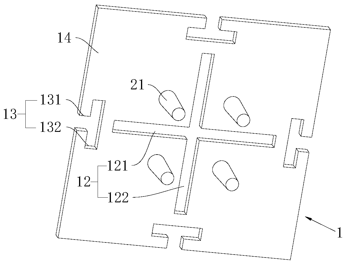
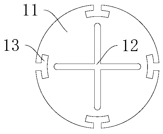
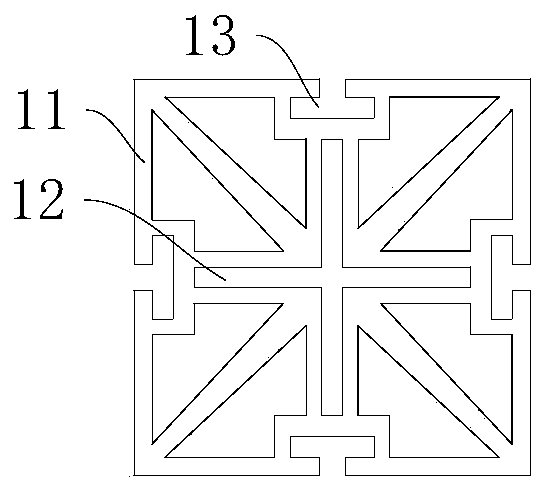
[0038] The present invention relates to a radiating structure, see Figure 1 to Figure 8 , is mainly used in the field of mobile communication antennas. By applying the radiation structure 1 to the antenna structure, the polarization isolation of the antenna can be improved. The refined and in-depth coverage and the development of the 5G era provide reliable resources.

[0039] Please combine figure 1 , the radiating structure 1 includes a radiating sheet 11 and a feeding column 14 for connecting the radiating sheet 11 and a feeding ne...


PUM


Abstract

The invention provides a radiation structure and an array antenna. The radiation structure comprises a radiation fin with a radiation slot in the middle. The radiation slot consists of a transverse slot and a longitudinal slot, which are communicated with each other and are cross-orthogonal. The length of the transverse slot and the length of the longitudinal slot are less than the length of the radiation fin in the extending direction of the corresponding radiation slot. By adding the radiation slot to the radiation fin, the radiation structure can produce two kinds of radiation synchronouslywhen working in an antenna system, so as to achieve an effect of polarization vector superposition enhancement. Thus, the same radiation efficiency and radiation gain of the multi-layer patch structure in the traditional antenna can be achieved by only one layer of radiation fin, fewer components are used, the structure is simple, the antenna profile can be reduced, and antenna miniaturization isfacilitated.

Description

technical field [0001] The invention relates to the field of mobile communication antennas, in particular to a radiation structure, a microstrip antenna unit and an array antenna. Background technique [0002] With the refined and deep coverage of mobile communication networks, the trial commercial use of 5G networks, the deployment of large-scale array antennas in the future, and the gradual integration of base station main equipment and antennas, communication systems have put forward new requirements for the miniaturization and weight reduction of antennas. higher requirement. [0003] The primary problem to be solved in 5G communication technology is how to realize large-scale and lightweight array antenna design. In the traditional MIMO system, the distance between the antennas is large and the mutual coupling is weak, so it is often possible to use metal die-casting oscillators with relatively stable structural performance but large volume and mass; however, in the 5G...

Claims


Application Information

Patent Timeline
Patent Type & Authority Applications(China)
IPC IPC(8): H01Q1/36H01Q1/50H01Q1/52H01Q13/10H01Q15/24H01Q19/10H01Q21/00H01Q21/06
CPCH01Q1/36H01Q1/52H01Q1/50H01Q1/523H01Q15/24H01Q13/10H01Q19/104H01Q21/0006H01Q21/061H01Q1/246H01Q21/26H01Q9/26
Inventor 李明超吕鹏飞宋建平
Owner COMBA TELECOM TECH (GUANGZHOU) CO LTD
Why Eureka
Try Eureka