Portable adjustable sucker

A portable, sucker technology, applied in the secondary processing of printed circuits, electrical components, printed circuit manufacturing, etc., can solve the problems of loss of adsorption force and air leakage of the cover film, and achieve the effect of easy implementation, reduced switching time, and simple operation.

Pending Publication Date: 2019-08-06
DALIAN JIXING ELECTRONICS
0 Cites 0 Cited by

AI-Extracted Technical Summary

Problems solved by technology

With the continuous development of the industry, the application fields of FPC continue to increase, and the demand continues to increase; when the flexible circuit board is automatically attached to the cover film, the suction cup will be used. Due to the different sizes of the flexible c...

Abstract

The invention discloses a portable adjustable sucker, which consists of an upper sucker and a lower sucker. The upper sucker is provided with an air exhaust slot inside and locking grooves on both sides. Air suction holes (a) are distributed in the bottom plate of the upper sucker. Upper sucker guide slots are arranged on the two sides of the lower part of the bottom plate. The lower sucker is provided with protruding edges on both sides, which are located in the corresponding upper sucker guide slots. Air suction holes (b) are distributed in the bottom plate of the lower sucker. The upper sucker is provided with an upper sucker fixed handle at one end, and the lower sucker is provided with a lower sucker fixed handle at one end. The upper sucker fixed handle is provided with a screw hole(a), and the lower sucker fixed handle is provided with a set of screw holes (b). A fixing screw passes through the screw hole (a) and one of the screw holes (b) to fix the upper and lower suckers. The time for replacement of different types of suckers is saved, and the production efficiency is improved.

Application Domain

Non-metallic protective coating application

Technology Topic

Engineering

Image

  • Portable adjustable sucker
  • Portable adjustable sucker
  • Portable adjustable sucker

Examples

  • Experimental program(1)

Example Embodiment

[0015] The present invention will be further described in detail below with reference to the drawings and specific embodiments: take this as an example to further describe the application.
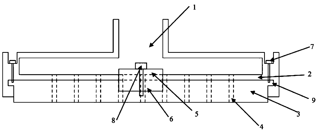
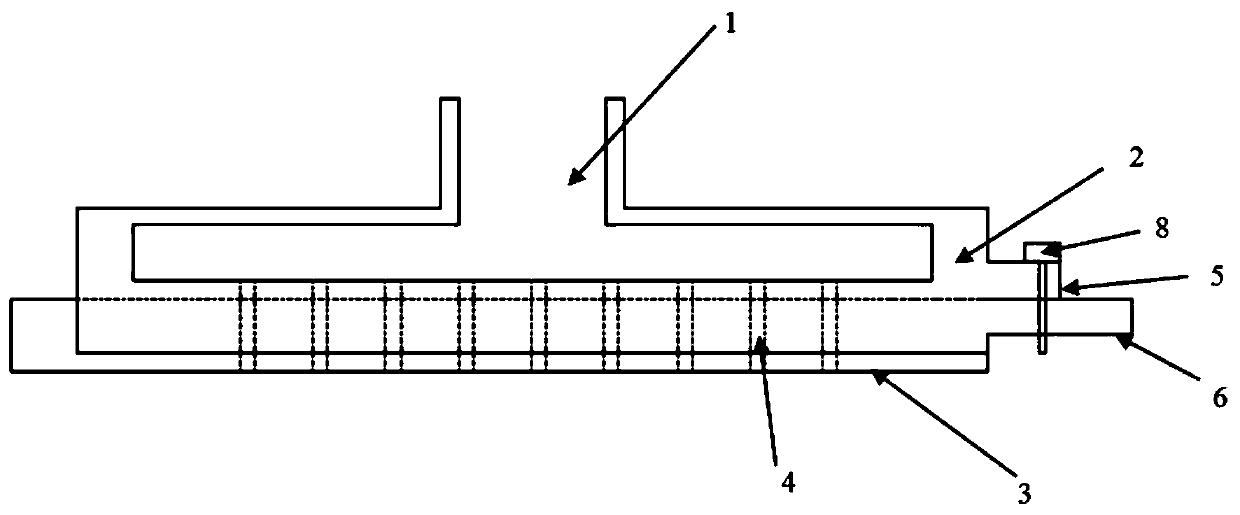
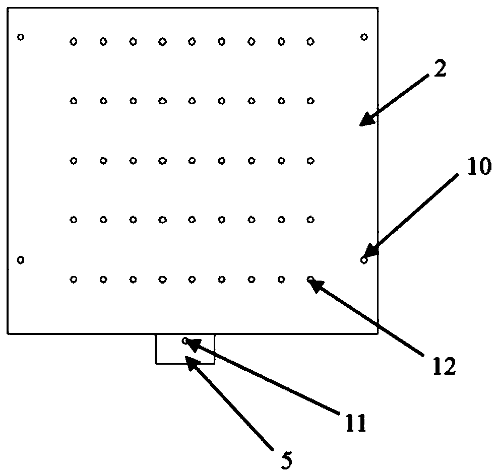
[0016] This embodiment provides a portable adjustable suction cup, including: an upper suction cup and a lower suction cup; the upper suction cup is provided with suction grooves inside, and locking grooves are provided on both sides of the upper suction cup, and the suction holes a are distributed on the upper suction cup On the bottom plate of the bottom plate, upper suction cup guide grooves are provided on both sides of the bottom of the bottom plate; both sides of the lower suction cup are provided with convex edges, which are respectively located in the corresponding upper suction cup guide grooves, and the suction holes b are distributed on the bottom plate of the lower suction cup An upper suction cup fixing handle is provided at one end of the upper suction cup, a lower suction cup fixing handle is provided at one end of the lower suction cup, the upper suction cup fixing handle is provided with screw holes a, and the lower suction cup fixing handle is provided with a set of screw holes b , The fixing screw passes through the screw hole a and one of the screw holes b to fix the upper suction cup and the lower suction cup. There are locking screw holes a around the upper suction cup, and the locking screw holes a are connected to the locking groove; there are a set of locking screw holes b around the lower suction cup, and the locking screws pass through the locking screw holes a. Lock the upper suction cup and the lower suction cup with the corresponding locking screw hole b. There are multiple rows of suction holes a uniformly distributed on the bottom plate of the upper suction cup; multiple rows of suction holes b are uniformly distributed on the bottom plate of the lower suction cup, and the number of each row of suction holes b increases sequentially from both sides to the middle. The suction hole a and part of the suction hole b form a connected suction hole. The number of lower suction cup locking screw holes b corresponds to the number of lower suction cup screw holes b. Different lower suction cup screw holes b correspond to different lower suction cup locking screw holes b; different screw holes b correspond to different suction cup widths; according to different sizes of flexibility On the circuit board, the suction holes b of the corresponding size are arranged on the lower suction cup.
[0017] In this application, the upper suction cup is fixed on the suction cup holder; the suction length of the suction cup is fixed, and the width of the suction cup can be adjusted according to the front and back movement of the lower suction cup. Insert the lower suction cup along the upper suction cup guide groove and adjust the bottom according to the required width Position the suction cup so that the lower suction cup screw hole b is aligned with the upper suction cup screw hole a, and the fixing screw passes through the upper suction cup screw hole a and the lower suction cup screw hole b to fix the position of the lower suction cup, and at the same time the corresponding lower suction cup suction hole b coincides with the upper suction hole a to control the suction width of the suction cup. Then use the locking screw to lock the upper and lower suction cups.
[0018] The above are only to create preferred specific implementations of the present invention, but the scope of protection created by the present invention is not limited to this. Anyone familiar with the technical field within the technical scope disclosed by the present invention, according to the present invention The created technical solution and its inventive concept shall be replaced or changed equivalently, and shall be covered by the protection scope of the invention.

PUM

no PUM

Description & Claims & Application Information

We can also present the details of the Description, Claims and Application information to help users get a comprehensive understanding of the technical details of the patent, such as background art, summary of invention, brief description of drawings, description of embodiments, and other original content. On the other hand, users can also determine the specific scope of protection of the technology through the list of claims; as well as understand the changes in the life cycle of the technology with the presentation of the patent timeline. Login to view more.

Similar technology patents

Graphene film and preparation method therefor

Owner:CHANGZHOU FUXI TECH CO LTD

Driving working load calculation method of automobile driver

InactiveCN101690666AImprove accuracy and timelinessEasy to operate
Owner:BEIJING UNIV OF TECH

Classification and recommendation of technical efficacy words

  • easy to implement
  • easy to operate

Intelligent video monitoring method and system thereof

InactiveCN101635835AEasy to implementEasy system expansion
Owner:SHENZHEN XINYI TECH CO LTD

Voice call routing by dynamic personal profile

InactiveUS7653191B1less laboreasy to implement
Owner:MICROSOFT TECH LICENSING LLC

Lancet device

InactiveUS7303573B2inexpensively mass-producedeasy to operate
Owner:ABBOTT DIABETES CARE INC

Rapid and non-invasive optical detection of internal bleeding

InactiveUS20050065436A1easy to operaterapid and accurate result
Owner:HO WINSTON ZONH +2
Why Eureka
Try Eureka