Eureka AIR delivers breakthrough ideas for toughest innovation challenges, trusted by R&D personnel around the world.

Adjustable rolling-type sand and stone screening device

A screening device and rolling technology, which is applied in the direction of filter screen, solid separation, grille, etc., can solve the problems of unable to adjust, easy to block the screen holes, etc., achieve simple structure, avoid filter blockage, and easy and fast operation Effect

Inactive Publication Date: 2019-08-09
曾钰云
View PDF0 Cites 4 Cited by
  • Summary
  • Abstract
  • Description
  • Claims
  • Application Information

AI Technical Summary

Problems solved by technology

[0004] The purpose of the present invention is to provide an adjustable rolling sand screening device to solve the problem that the traditional filter screen is easy to block and the screen hole cannot be adjusted

Method used

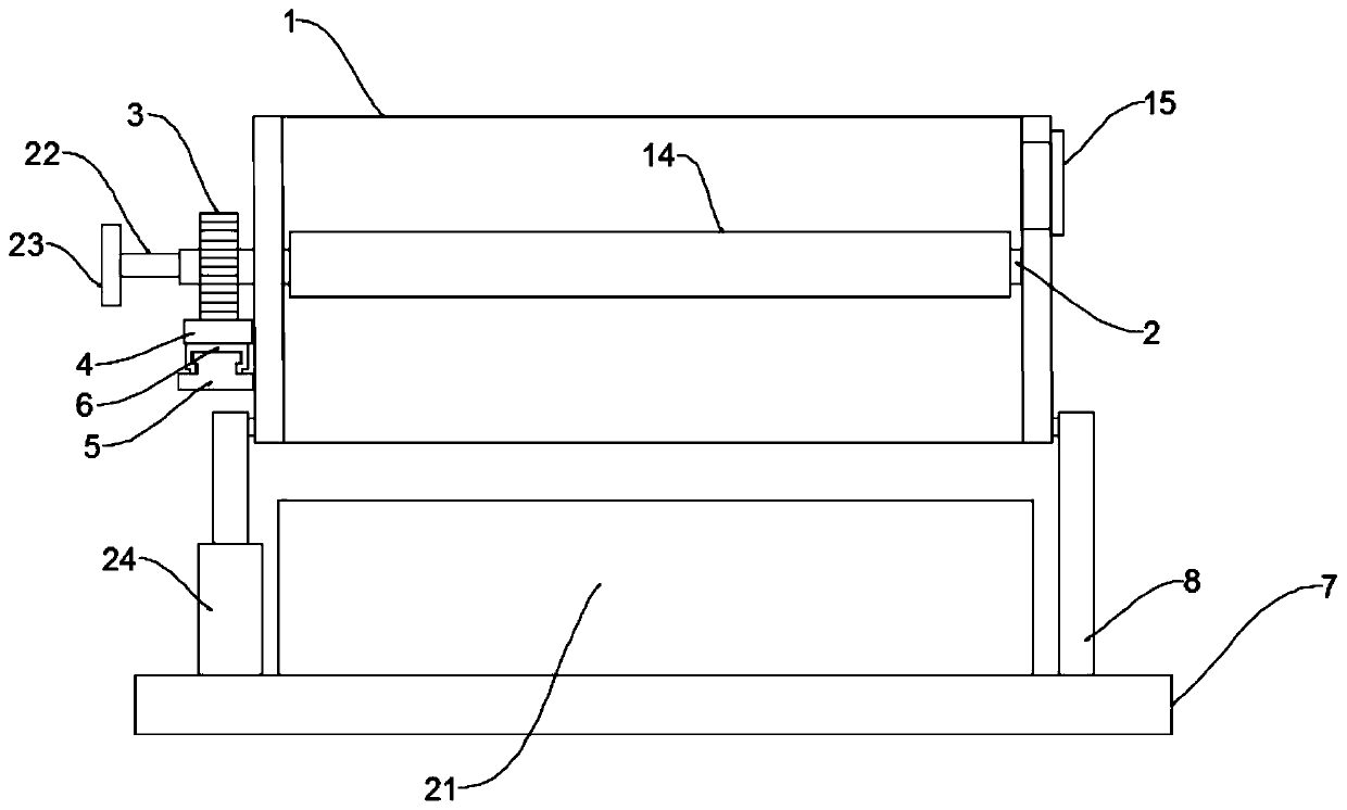

Image

  • Adjustable rolling-type sand and stone screening device
  • Adjustable rolling-type sand and stone screening device
  • Adjustable rolling-type sand and stone screening device

Examples


Embodiment 1

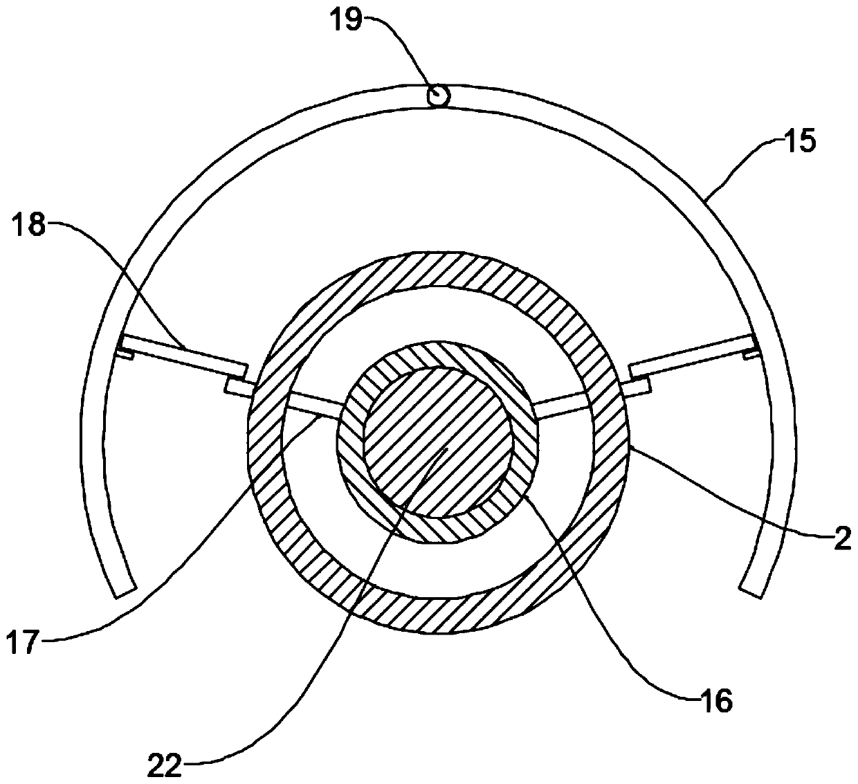
[0025] see figure 1 and 2 , in the embodiment of the present invention, an adjustable rolling sand screening device includes a screening channel 1 and a base substrate 7, the screening channel 1 is installed with the upper side of the base substrate 7, and the screening channel The inside of 1 is provided with a plurality of parallel rotating round rods 2, the axis distance between each rotating round rod 2 is equidistant and each rotating round rod 2 is provided with a baffle plate 14, and each rotating round rod 2 The ends protruding from the side wall of the screening channel 1 are all provided with driving gears 3, and the side of the screening channel 1 is provided with a rack 4 meshing with a plurality of driving gears 3, and the lower end of the rack 4 passes through the The sliding mechanism is connected to the side wall of the screening channel 1, specifically, a limiting guide rail 5 is fixed on the side wall of the screening channel 1, and the limiting guide rail 5...

Embodiment 2

[0029] The difference between the embodiment of the present invention and embodiment 1 is that a spiral sleeve 16 is provided on the side wall of the screening channel 1 away from the drive gear 3, and the bottom edge of the spiral sleeve 16 is located at the top wall of the baffle plate 14. On the same plane, one end of the bottom wall of the screening channel 1 is hinged to the upper end surface of the screening channel 1 through a support frame 8, and the other end of the bottom wall of the screening channel 1 is provided with a hydraulic cylinder 24. When the hydraulic cylinder 24 is activated, it can One end of the screening channel 1 is raised, and then the arc plate 15 is opened, so that the stones stranded on the baffle plate 14 are released from the arc plate 15, and it is more convenient to discharge the stones.

[0030] The upper end surface of the base plate 7 is also provided with a collecting tank 21 located directly below the screening channel 1 to facilitate the...


PUM


Abstract

The invention discloses an adjustable rolling-type sand and stone screening device, relates to the technical field of screening devices. The adjustable rolling-type sand and stone screening device mainly aims to solve the problems that a traditional screening device needs to turn over to discharge stones and the operation is inconvenient. The screening device comprises a screening through groove and a base substrate, wherein the inside of the screening through groove is provided with a plurality of parallel rotating round rods; the upper portion of each rotating round rod is provided with a baffle; the end portion of each rotating round rod extending out of the side wall of the screening through groove is provided with a driving gear; the sides of the screening through groove are providedwith racks engaged with the plurality of driving gears; and one end of the screening through groove is provided with a power assembly for driving the racks to horizontally reciprocate. The adjustablerolling-type sand and stone screening device is simple in structure, capable of avoiding filter screen type blockage, capable of adjusting the particle size of sand screening, simple, convenient and fast to operate and high in practicability.

Description

technical field [0001] The invention relates to the technical field of screening devices, in particular to an adjustable rolling sand screening device. Background technique [0002] Sand and gravel refers to a loose mixture of sand grains and gravel. In geology, mineral or rock particles with a particle size of 0.074-2mm are called sand, and those with a particle size larger than 2mm are called gravel or breccia (the difference between the two lies in the degree of rounding, see the entry conglomerate and sandstone for details. ). If most of the gravel in the sand is gravel, it is called sand gravel. Some people also refer to sandstone as sandstone in daily life. [0003] Sand and gravel are indispensable and important raw materials in construction. Due to the different particle sizes in sand and gravel, this will cause the fineness of sand and gravel in construction construction to fail to meet the requirements, so screening is required. Now Sand and gravel screening ba...

Claims


Application Information

Patent Timeline
Patent Type & Authority Applications(China)
IPC IPC(8): B07B1/14B07B1/46B07B1/42
CPCB07B1/14B07B1/42B07B1/46B07B1/4609
Inventor 曾钰云
Owner 曾钰云
Why Eureka
Eureka Blog
Learn More