Eureka AIR delivers breakthrough ideas for toughest innovation challenges, trusted by R&D personnel around the world.

Injection mold and application method thereof

An injection mold and mold flow technology, which is applied in the field of mold mechanism design, can solve the problems of difficulty in continuing the mold working cycle and the failure of demolding of runner waste, and achieve the effect of ensuring the automatic production function.

Inactive Publication Date: 2019-08-09
李睿
View PDF0 Cites 0 Cited by
  • Summary
  • Abstract
  • Description
  • Claims
  • Application Information

AI Technical Summary

Problems solved by technology

[0002] In the injection mold, when the three-plate mold structure mold is formed, the waste material of the point gate runner can be automatically stripped on the mold, and the small pull rod can be pulled through the fixed plate to pull the stripping plate to pull the waste material of the runner from the material installed on the panel. The runner waste is released from the rod to let it fall off automatically to realize the automatic production of the mold. However, with the different plastic materials, many plastics sometimes stick to each other after being demoulded from the mushroom head of the pull rod on the panel. If it cannot fall off on the runner plate, it will cause the demoulding failure of the entire runner waste, which will make it difficult to continue the working cycle of the mold. Therefore, it is necessary to design an automatic material removal auxiliary mechanism for this practical production problem. , to solve the above problem

Method used


Image

  • Injection mold and application method thereof
  • Injection mold and application method thereof

Examples


Embodiment Construction

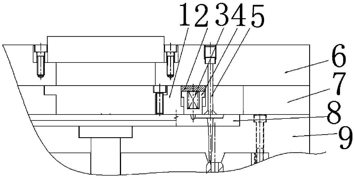
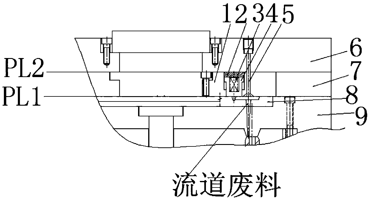
[0012] Figure 1-2 Shown is the relevant explanatory figure of the present invention; The specific embodiment is, as figure 1 , figure 2 As shown, an automatic spring material mechanism for the front mold of a three-plate mold injection mold includes a spring material insert block 1, a spring pressure plate 2, a spring 3, a spring pressure sleeve 4, a pull rod 5, a front mold panel 6, a runner plate 7, Front mold runner insert plate 8, front template 9.

[0013] In the mechanism, the bullet insert block 1 is fastened on the flow channel plate 7 by screws, and the bullet insert block 1 is provided with a hole for installing the elastic sleeve 4, and the elastic sleeve 4 is loaded into the bullet insert block 1 After entering the hole, its cooperation with the hole on the bullet insert block 1 is a sliding fit; the spring 3 is set in the hole of the spring sleeve 4, and it is pressed by the spring pressure plate 2, and the spring sleeve 4 is installed on the bullet. In the h...


PUM


Abstract

The invention provides an injection mold and an application method thereof. The injection mold comprises a three-plate-mold injection mold front mold automatic ejecting mechanism for solving the problem of halfway falling in the three-plate upper runner waste falling; the mechanism performs reliable demolding for the problem of variable plastic runner wastes attached on runner plates, and can realize automatic falling of various plastic from the runner plates without bonding on the runner plates to guarantee the mold automatic production function; and the mechanism is reasonable in design, compact in structure, stable in work, safe, reliable and convenient to use.

Description

technical field [0001] The invention relates to the field of mold mechanism design, in particular to an injection mold and a use method thereof. Background technique [0002] In the injection mold, when the three-plate mold structure mold is formed, the waste material of the point gate runner can be automatically stripped on the mold, and the small pull rod can be pulled through the fixed plate to pull the stripping plate to pull the waste material of the runner from the material installed on the panel. The runner waste is released from the rod to let it fall off automatically to realize the automatic production of the mold. However, with the different plastic materials, many plastics sometimes stick to each other after being demoulded from the mushroom head of the pull rod on the panel. If it cannot fall off on the runner plate, it will cause the demoulding failure of the entire runner waste, which will make it difficult to continue the working cycle of the mold. Therefore,...

Claims


Application Information

Patent Timeline
Patent Type & Authority Applications(China)
IPC IPC(8): B29C45/38
CPCB29C45/38
Inventor 不公告发明人
Owner 李睿
Why Eureka
Eureka Blog
Learn More