Eureka AIR delivers breakthrough ideas for toughest innovation challenges, trusted by R&D personnel around the world.

Cutting device for silicon single crystal rod

A technology of cutting device and single crystal silicon rod, which is applied to fine working devices, working accessories, stone processing equipment, etc., can solve problems such as poor working environment, uneven cutting surface, and inability to effectively control cutting thickness, and achieve stable cutting. , The effect of preventing sparks from splashing and improving service life

Inactive Publication Date: 2021-06-22
王慧芝
View PDF0 Cites 0 Cited by
  • Summary
  • Abstract
  • Description
  • Claims
  • Application Information

AI Technical Summary

Problems solved by technology

[0002] Monocrystalline silicon is an important part of crystalline materials and is at the forefront of the development of new materials. It is used to make high-power rectifiers, high-power transistors, diodes, switching devices, etc. It is a promising material in the development of energy. In industrial production, silicon rods grow rod-shaped single crystal silicon from the furnace body by using the Czochralski method or suspension zone melting method. Some monocrystalline silicon rod cutting devices manually push the single crystal silicon rod for cutting, the cutting thickness cannot be effectively controlled, some are thick, some are thin, and the cutting surface is prone to unevenness, which is insufficient There will be sparks and dust, and the working environment is poor

Method used


Image

  • Cutting device for silicon single crystal rod
  • Cutting device for silicon single crystal rod
  • Cutting device for silicon single crystal rod

Examples


Embodiment Construction

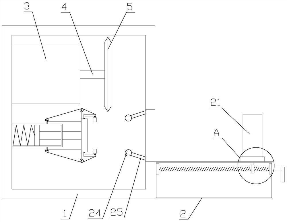
[0026] The present invention is described in further detail now in conjunction with accompanying drawing. These drawings are all simplified schematic diagrams, which only illustrate the basic structure of the present invention in a schematic manner, so they only show the configurations related to the present invention.

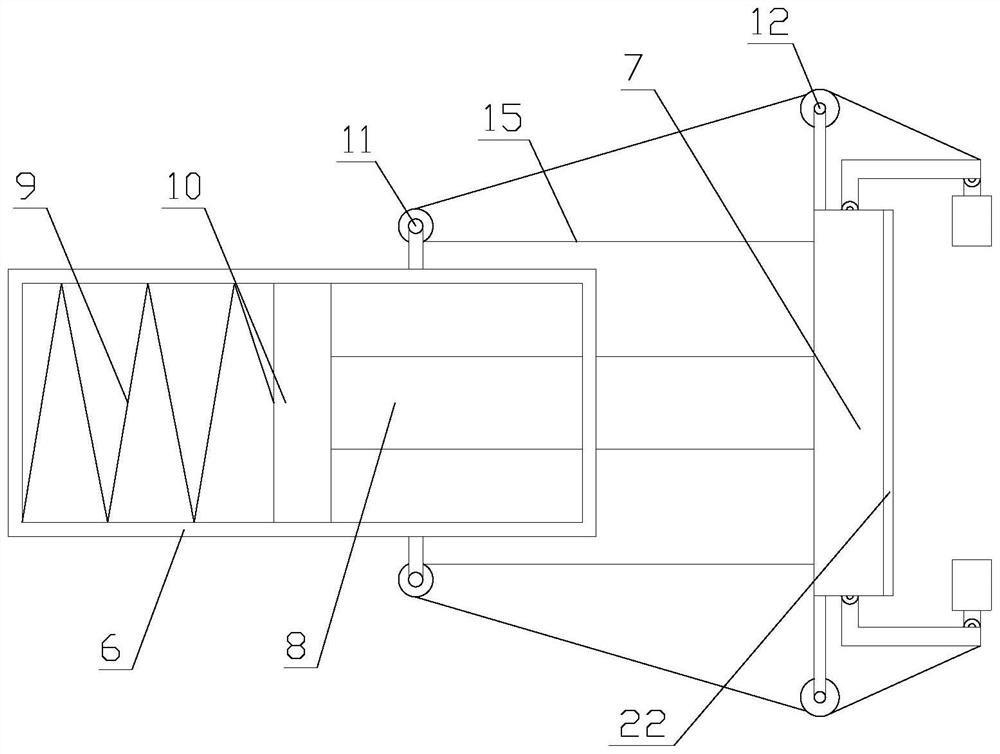
[0027] like figure 1 As shown, a cutting device for monocrystalline silicon rods includes a fixed box 1, a base 2, a cutting mechanism, a moving mechanism and a clamping mechanism, the fixed box 1 is vertically arranged, and the base 2 is horizontally arranged on a fixed One side of the bottom end of the box 1, the cutting mechanism and the clamping mechanism are both arranged in the fixed box 1, the cutting mechanism is located above the clamping mechanism, and the moving assembly is arranged on the base 2;

[0028] The cutting mechanism includes a drive box 3, a rotating rod 4 and a blade 5, the drive box 3 is horizontally arranged on the inner wall of the ...


PUM


Abstract

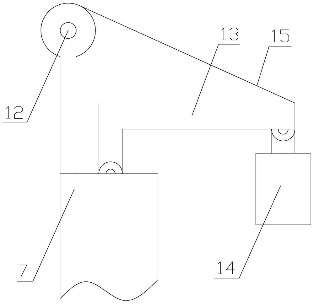
The invention relates to a cutting device for a silicon single crystal rod. The cutting device comprises a fixed box, a base, a cutting mechanism, a moving mechanism and a clamping mechanism, wherein the cutting mechanism comprises a driving box, a rotating rod and a blade, the clamping mechanism comprises a piston cylinder, an abutting plate, a moving rod, a spring, a piston and a clamping assembly, and the moving mechanism comprises a lead screw, a bearing seat, a walking ring, a connecting rod, a moving block and a positioning box. By using the cutting device for the silicon single crystal rod, movement of a main body and control on the cutting amount of the main body are both achieved through the moving mechanism, so that the cutting size of the main body is conveniently adjusted; the main body is automatically clamped through the clamping mechanism and can automatically fall off through restoring force of the spring without disassembling the main body by opening the fixed box for multiple times, so that the use practicability is improved; and in addition, the clamping mechanism herein is of a pure mechanical structure and clamps the main body through thrust of the main body, so that the service life is prolonged.

Description

technical field [0001] In particular, the invention relates to a cutting device for monocrystalline silicon rods. Background technique [0002] Monocrystalline silicon is an important part of crystalline materials and is at the forefront of the development of new materials. It is used to make high-power rectifiers, high-power transistors, diodes, switching devices, etc. It is a promising material in the development of energy. In industrial production, silicon rods grow rod-shaped single crystal silicon from the furnace body by using the Czochralski method or suspension zone melting method. Some monocrystalline silicon rod cutting devices manually push the single crystal silicon rod for cutting, the cutting thickness cannot be effectively controlled, some are thick, some are thin, and the cutting surface is prone to unevenness, which is insufficient There will be sparks and dust, and the working environment is poor. Contents of the invention [0003] The technical problem...

Claims


Application Information

Patent Timeline
IPC IPC(8): B28D5/02B28D7/04B28D7/00
CPCB28D5/0058B28D5/0082B28D5/02
Inventor 王慧芝
Owner 王慧芝
Why Eureka
Eureka Blog
Learn More