High-frequency composite electronic universal testing machine

A universal testing machine, high-frequency technology, applied in the field of testing machines, can solve the problems of cumbersome operation, low equipment utilization, low efficiency and so on

Pending Publication Date: 2019-08-09
长春浩园试验机有限公司
View PDF0 Cites 2 Cited by
  • Summary
  • Abstract
  • Description
  • Claims
  • Application Information

AI Technical Summary

Problems solved by technology

[0003] The purpose of the present invention is to propose a high-frequency composite electronic universal testing machine, which solves the problems of cumbersome operation, low efficiency and low utilization rate of equipment in the prior art; it integrates electromagnetic high-frequency test, electronic universal test and electromagnetic vibrating table into one On one piece of equipment, a variety of test operations are completed on a composite testing machine

Method used


Image

  • High-frequency composite electronic universal testing machine
  • High-frequency composite electronic universal testing machine
  • High-frequency composite electronic universal testing machine

Examples


Embodiment Construction

[0039] Embodiments of the present invention will be further described below in conjunction with the accompanying drawings.

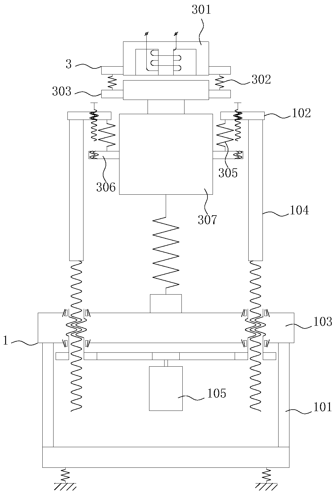
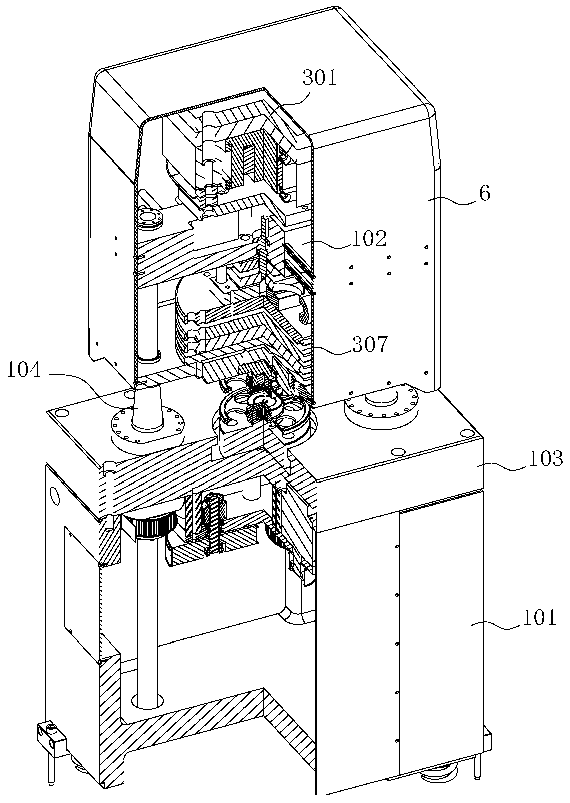
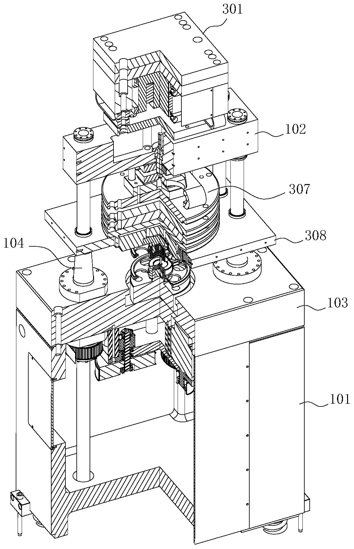
[0040] See attached figure 1 - attached Figure 4 And attached Figure 8 , the high-frequency composite electronic universal testing machine of the present invention comprises:

[0041] A frame 1, said frame 1 at least comprising an upper crossbeam 102 and a lower crossbeam 103 which are arranged oppositely in the height direction and relatively move in parallel;

[0042] The clamp 2 arranged between the upper beam 102 and the lower beam 103, the clamp 2 includes an upper clamp 201 and a lower clamp 202 arranged oppositely in the height direction of the frame 1, the lower clamp 202 and the lower beam 103 fixed connections;

[0043] The electromagnetic high-frequency vibration excitation mechanism 3 arranged on the upper beam 102, the electromagnetic high-frequency vibration excitation mechanism 3 passes through the upper beam 102 through the connecti...


PUM


Abstract

The invention provides a high-frequency composite electronic universal testing machine, belongs to the technical field of testing machines, and aims to solve the problems of cumbersome operation, lowefficiency and low utilization rate of equipment in the prior art. The high-frequency composite electronic universal testing machine comprises a machine frame, a clamp, an electromagnetic high-frequency excitation mechanism, a conversion mechanism and a cage structure, wherein the machine frame at least comprises an upper beam and a lower beam which are oppositely arranged in the height directionand move in parallel relatively. The clamp is arranged between the upper beam and the lower beam, the clamp comprises an upper clamp and a lower clamp which are oppositely arranged in the height direction of the machine frame, and the lower clamp is fixedly connected with the lower beam. The electromagnetic high-frequency excitation mechanism is arranged on the upper beam, and the electromagnetichigh-frequency excitation mechanism penetrates through the upper beam through connecting columns and is fixedly connected with the upper clamp. The connecting columns relative to the upper beam are switched in a fixed state and a free state by the conversion mechanism. The upper clamp and the lower clamp are detachably connected to the two ends of the cage structure correspondingly.

Description

technical field [0001] The invention belongs to the technical field of testing machines, and in particular relates to a high-frequency composite electronic universal testing machine. Background technique [0002] In the prior art, materials, components or devices in many fields need to be tested for stability before actual use to determine the reliability of their quality. In the prior art, structures used for mechanical testing of materials, components or devices have Electromagnetic high-frequency testing machine, electronic universal testing machine and electromagnetic vibration table, etc. All three have a wide range of uses. However, different equipment needs to be replaced when performing various mechanical tests on a DUT, which is cumbersome to operate and low in efficiency. At the same time, the utilization rate of a single equipment is also low. Contents of the invention [0003] The purpose of the present invention is to propose a high-frequency composite electr...

Claims


Application Information

Patent Timeline
Patent Type & Authority Applications(China)
IPC IPC(8): G01N3/08G01N3/38G01N3/04
CPCG01N3/04G01N3/08G01N3/38G01N2203/0017G01N2203/0019G01N2203/005G01N2203/04
Inventor 张学成逯志坚
Owner 长春浩园试验机有限公司
Why Eureka
Try Eureka