
Electronic pen

An electronic pen and pen tip technology, which is applied to the input/output process of electrical digital data processing, instruments, and data processing, etc., can solve the problems of difficult production and application, high cost of pressure sensors, and achieve cost savings, improved sensitivity, and reduced accuracy. effect of demand

Pending Publication Date: 2019-08-09
北京科加触控技术有限公司
View PDF0 Cites 1 Cited by
  • Summary
  • Abstract
  • Description
  • Claims
  • Application Information

AI Technical Summary

Problems solved by technology

However, the production, procurement and maintenance costs of pressure sensors with high acquisition accuracy are relatively high, which puts certain pressure on developers and purchasers, and it is difficult to achieve large-scale production applications

Method used


Image

  • Electronic pen
  • Electronic pen
  • Electronic pen

Examples


Embodiment 1

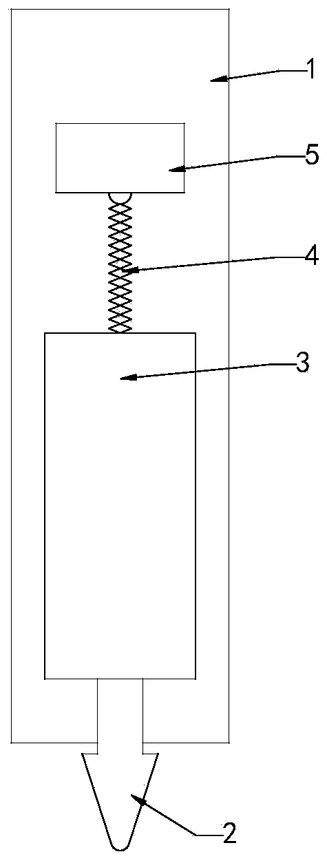
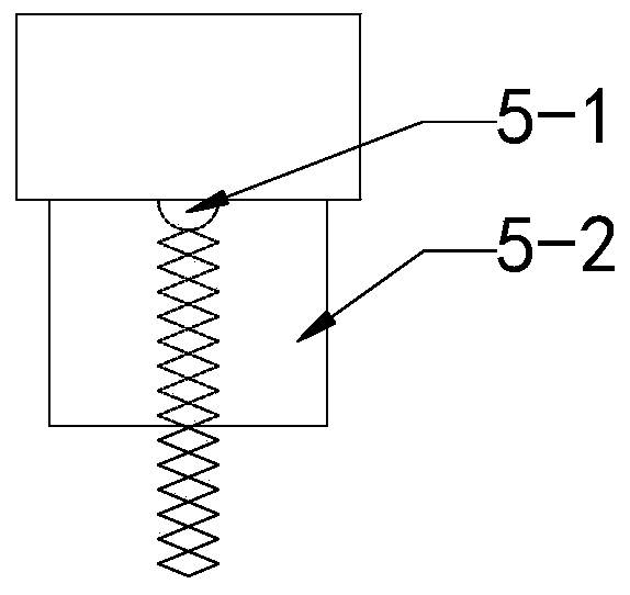
[0041] Such as figure 1 As shown, the piston part 3 is arranged inside the pen holder 1 and above the pen tip 2. The bottom of the piston part 3 is fixedly connected with the top of the pen tip 2. The pressure sensor 5 is located above the piston part 3, and the pressure collection point 5-1 of the pressure sensor 5 is connected to the top of the piston part 3 through an elastic member 4. At this time, the piston part 3 corresponds to a transmission mechanism. When a user uses an electronic pen to write, the pen tip 2 is in contact with the display of the touch device and receives force, so that the pen tip 2 moves toward the inner direction of the pen holder 1. Since the piston part 3 and the pen tip 2 are fixed together, the piston part 3 also moves in the direction of the elastic member 4, thereby compressing the elastic member 4. At this time, the pressure received by the nib 2 is applied to the pressure sensor 5 through the piston part 3 and the elastic member 4, and due...

Embodiment 2

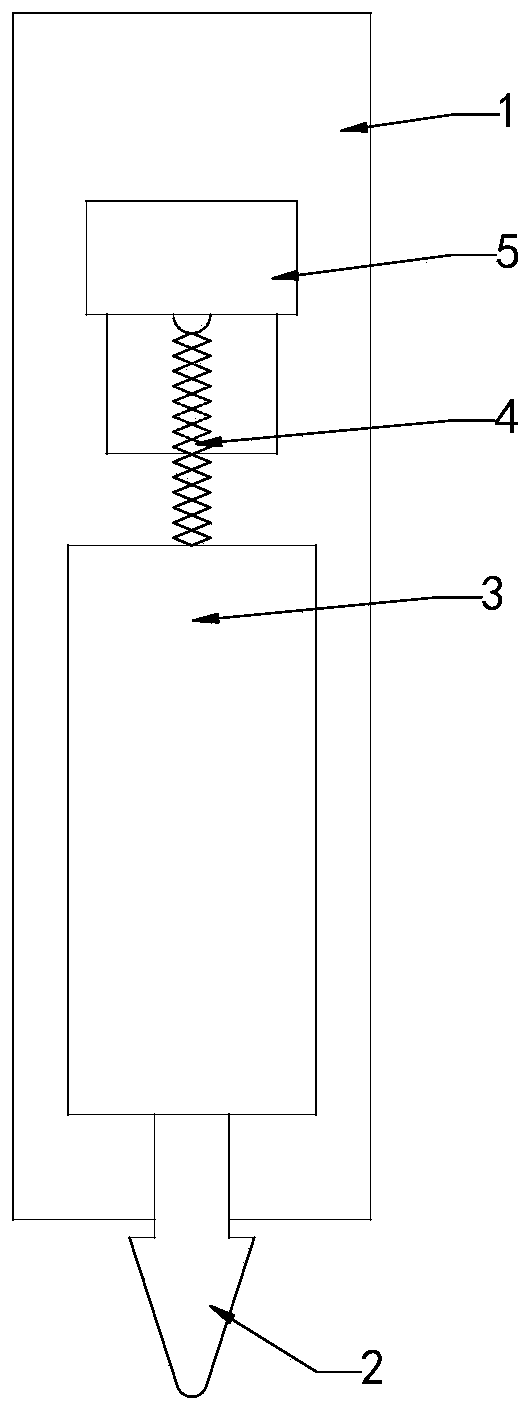
[0048] Such as Image 6 As shown, the piston part 3 is arranged inside the pen holder 1 and above the pen tip 2. The bottom of the piston part 3 is fixedly connected to the top of the pen tip 2, and the outer wall of the piston part 3 is fixedly connected to the inner wall of the pen holder 1. The pressure sensor 5 is located above the piston part 3, and the pressure collection point 5-1 of the pressure sensor 5 is connected to the top of the piston part 3 through an elastic member 4. At this time, the piston part 3 corresponds to a transmission mechanism. When a user uses an electronic pen to write, the pen tip 2 is in contact with the display of the touch device and receives force, so that the pen tip 2 moves toward the inner direction of the pen holder 1. Since the piston part 3 and the pen tip 2 are fixed together, the piston part 3 also moves in the direction of the elastic member 4, thereby compressing the elastic member 4. At this time, the pressure received by the nib...


PUM


Abstract

The invention provides an electronic pen which comprises a pen point and a nib, the pen point is arranged at the front end of a pen container, and a piston part, an elastic part and a pressure sensorare arranged in the pen container. The top of the pen point is fixedly connected with the bottom of the piston part, the outer wall of the piston part is fixedly connected with the inner wall of the pen container, and the pressure sensor is arranged above the piston part; the elastic component is connected between a pressure collecting point of the pressure sensor and the top of the piston part, and the pen point can change the contraction or elongation of the elastic component through the piston part under the action of the external forces or the own gravity of the pen point. The electronic pen of the invention is suitable for amplifying the stroke of the pressure sensor in the electronic pen.

Description

Technical field [0001] This application relates to smart electronic devices, and in particular to an electronic pen. Background technique [0002] With the improvement of the level of technology and the quality of life, more and more smart devices appear in people's daily work and life, and touch devices are one of them. People can directly operate on the display screen through the touch device, without a mouse or other devices for wired or wireless operation, which is convenient and quick. At the same time, writing devices capable of writing on touch devices have also emerged. People can write freely on touch devices like pens by using writing devices. [0003] In order to provide users with a better and more realistic writing effect, major manufacturers have installed pressure sensors in their writing devices. The design of the pressure sensor can be used as a basis for judging whether writing occurs on the one hand, and on the other hand, the thickness of the writing handwrit...

Claims


Application Information

Patent Timeline
Patent Type & Authority Applications(China)
IPC IPC(8): G06F3/0354G06F3/041
CPCG06F3/03545G06F3/0414
Inventor 吴振宇王宇辉
Owner 北京科加触控技术有限公司
Learn More