
Power transformer fault deduction method

A power transformer and fault technology, applied in the field of power transformer fault derivation, can solve the influence of not considering the correctness of the extraction of the state feature association of the sample balanced transformer, the robustness of the state evaluation needs to be improved, and the internal correlation complex is not effectively taken into account. Association rules complexity and other issues

Pending Publication Date: 2019-08-09
SHANGHAI MUNICIPAL ELECTRIC POWER CO
View PDF1 Cites 4 Cited by
  • Summary
  • Abstract
  • Description
  • Claims
  • Application Information

AI Technical Summary

Problems solved by technology

[0006] However, when the above-mentioned analytical state evaluation method performs mapping correlation weight analysis and calculation on fault types / symptoms, it usually adopts the expert comprehensive scoring method and the analytic hierarchy process with strong subjective dependence, so it still needs the support of subjective experience; while the existing fusion correlation Although the intelligent algorithm of rules improves the subjectivity of expert comprehensive scoring and AHP in the process of association rule mining and weight calculation, it does not effectively take into account the inherent correlation between fault symptoms and the complexity of compound association rules. It also does not consider the influence of sample balance on the correctness of transformer state feature correlation extraction; while the extension analysis based on matter-element correlation introduces the idea of ​​matter-element correlation in the degradation analysis, effectively considering the state parameters of the transformer in the normal and fault value intervals. However, the evaluation process still needs the accumulation and support of expert systems and empirical knowledge, and the robustness of its state evaluation needs to be improved.

Method used


Image

  • Power transformer fault deduction method
  • Power transformer fault deduction method
  • Power transformer fault deduction method

Examples


Embodiment

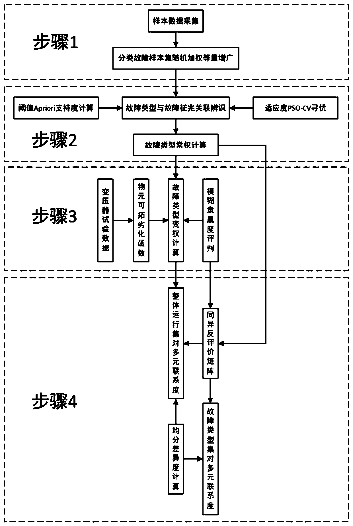
[0218] In order to verify the correctness and effectiveness of the present invention, a 220kV oil-immersed power transformer (SFPS9-180000 / 220) in a substation is taken as an example for analysis. By consulting the relevant information of this transformer, it is found that the corresponding 24 state quantities in Table 2 and Table 3 all exist. The historical test data of transformers that are similar to the operating environment of the tested transformer and known fault types are sorted out and analyzed, and the results of equal expansion of the classified fault sample set by the random bootstrap method are shown in Table 5. It can be seen from Table 5 that the obtained fault sample augmentation results corresponding to each fault type are roughly equivalent, and can be further used for fault correlation mapping deduction of transformers. Among them, before the separator " / " is the number of failure symptoms exceeding the standard, and after " / " is the corresponding support. ...


PUM


Abstract

The invention discloses a power transformer fault deduction method, which fuses the substance element augmented extension association mining and fuzzy set pair analysis, improves the influence of thesample set imbalance on the correctness of transformer state feature association extraction, reduces the influence of subjective dependence of a constant weight calculation process on transformer fault diagnosis and state evaluation effectiveness, provides a clearer and more objective theoretical guidance for the field operators to clearly quantify the internal association between the power transformer fault symptom and the fault type, provides the reliable theoretical and technical supports for the operators to select operation and maintenance overhaul means, realize power transformer fault backtracking and improve fault positioning analysis efficiency, and provides the solid technical support for the further online real-time deduction and the rapid hidden danger positioning of the powertransformer fault based on the virtual reality technology, and guarantees the safe and stable operation of a power system.

Description

technical field [0001] The invention relates to a power transformer fault deduction method. Background technique [0002] The working status of power transformers, especially oil-immersed power transformers, is an important reference for evaluating the safety and reliability of their operation. Power transformer failure may lead to serious power system blackout accidents. After decades of development, power transformer inspection and diagnosis technology has gone through two main stages of post-event maintenance and preventive maintenance. The purpose of reducing the power transformer failure and power system blackout accidents, reducing the power outage time, saving manpower and material resources, and improving the intelligent level of power grid operation and inspection. Therefore, it is particularly important to detect potential initial faults and evaluate the working status of power transformers, which is an important technical means to prevent and avoid serious faults...

Claims


Application Information

Patent Timeline
Patent Type & Authority Applications(China)
IPC IPC(8): G06K9/62
CPCG06F18/2433G06F18/241G06F18/214
Inventor 邵宇鹰彭鹏高宇博罗潇陈婷俞玮庄贝妮马鲁
Owner SHANGHAI MUNICIPAL ELECTRIC POWER CO
Learn More