
Method for calculating highest temperature of shell of power chip

A technology of power chips and calculation methods, applied in thermometers, applications of thermometers, and parts of thermometers, etc., can solve problems such as different TCmax values, poor shell accuracy, and increased cost of heat sinks

Active Publication Date: 2019-08-13
AMOLOGIC (SHANGHAI) CO LTD
View PDF9 Cites 0 Cited by
  • Summary
  • Abstract
  • Description
  • Claims
  • Application Information

AI Technical Summary

Problems solved by technology

[0008] Problem 1, the accuracy of the calculated maximum temperature of the chip shell is poor. The reason is that the TCmax value calculated in the standard rule (spec) is obtained by simulation calculation on a standard PCB board and a standard laboratory environment, but There are not small differences in the PCB size of the main board in the actual application and the heat dissipation environment of the actual product structure, which leads to errors in the calculated TCmax value;
[0009] The second problem is that the test position of the chip has not been determined, and the test position of the chip will lead to different TCmax values. For example, the edge temperature of the chip is generally lower than the center point temperature
[0010] Therefore, the above method can avoid the above problems by increasing the derating margin (that is, increasing the size of the heat sink, the margin will be increased to 10% to 30% in the actual project), but increasing the derating margin will lead to an increase in the cost of the heat sink

Method used


Image

  • Method for calculating highest temperature of shell of power chip
  • Method for calculating highest temperature of shell of power chip

Examples


Embodiment Construction

[0051] The following will clearly and completely describe the technical solutions in the embodiments of the present invention with reference to the accompanying drawings in the embodiments of the present invention. Obviously, the described embodiments are only some, not all, embodiments of the present invention. Based on the embodiments of the present invention, all other embodiments obtained by persons of ordinary skill in the art without creative efforts fall within the protection scope of the present invention.

[0052] It should be noted that, in the case of no conflict, the embodiments of the present invention and the features in the embodiments can be combined with each other.

[0053] The present invention will be further described below in conjunction with the accompanying drawings and specific embodiments, but not as a limitation of the present invention.

[0054] The invention includes a method for calculating the maximum temperature of a power chip shell, which is a...


PUM


Abstract

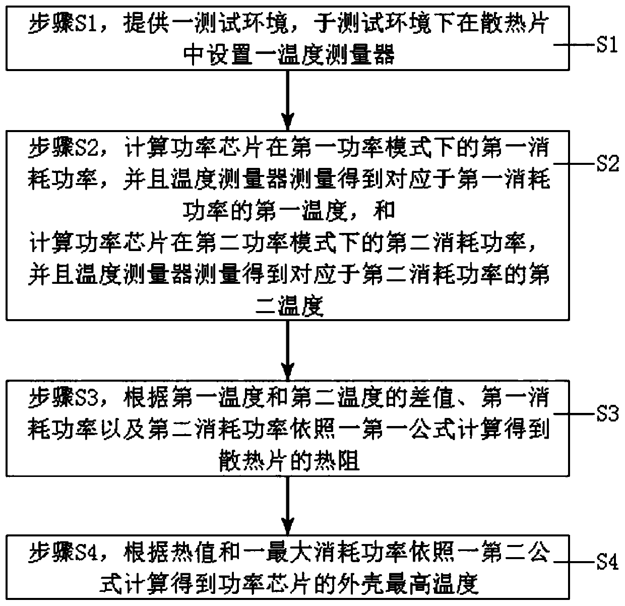
The invention provides a method for calculating the highest temperature of a shell of a power chip. The method comprises the steps of: S1, providing a test environment, and arranging a temperature measurer in a radiating fin in the test environment; S2, calculating the first consumption power of the power chip in a first power mode, measuring a first temperature corresponding to the first consumption power by employing the temperature measurer, calculating a second consumption power of the power chip in a second power mode, and measuring a second temperature corresponding to the second consumption power by the temperature measurer; S3, calculating the thermal resistance of the radiating fin according to the difference value of the first temperature and the second temperature, the first consumption power and the second consumption power according to a first formula; and S4, calculating the highest temperature of the shell of the power chip according to the heat value and the maximum power consumption and according to a second formula. The method saves the estimation time, improves the production efficiency and reduces the production cost.

Description

technical field [0001] The invention relates to the field of chip technology, in particular to a method for calculating the maximum temperature of a power chip shell. Background technique [0002] In order to ensure the stable operation of the system, the current electronic equipment usually cools down the chips with relatively large power consumption (such as SOC main chip, PowerIC, etc.) The use of will increase the risk of system stability, so how to quickly estimate the thermal resistance of the heat sink has become an urgent problem to be solved. [0003] In the prior art, the following two methods are used to calculate the heat sink: [0004] Method 1: Use simulation tools to simulate and calculate the thermal resistance of the heat sink required by the power chip. However, the simulation calculation needs to collect various influencing parameters, and the entire simulation calculation process is cumbersome, time-consuming and laborious; especially for multiple produc...

Claims


Application Information

Patent Timeline
IPC IPC(8): G01K13/00G01K1/14G01R21/02G01N25/20
CPCG01K13/00G01K1/14G01R21/02G01N25/20
Inventor 韩小江张坤黄敏君
Owner AMOLOGIC (SHANGHAI) CO LTD
Learn More