Optical device for detecting optical diffractive element based on mutual capacitance

A technology of optical diffraction elements and optical devices, which is applied in the direction of optical elements, optics, and the use of electric/magnetic devices to transmit sensing components, etc., and can solve problems such as increased process difficulty

Pending Publication Date: 2019-08-13
NINGBO SUNNY OPOTECH CO LTD
View PDF5 Cites 4 Cited by
  • Summary
  • Abstract
  • Description
  • Claims
  • Application Information

AI Technical Summary

Problems solved by technology

In addition, due to the existence of such a gap layer, it is necessary to ensure g

Method used


Image

  • Optical device for detecting optical diffractive element based on mutual capacitance
  • Optical device for detecting optical diffractive element based on mutual capacitance
  • Optical device for detecting optical diffractive element based on mutual capacitance

Examples


Embodiment Construction

[0030] Certain exemplary embodiments will now be described in more detail with reference to the accompanying drawings, wherein like reference numerals refer to like elements throughout. In this regard, exemplary embodiments may have different forms and should not be construed as being limited to the descriptions set forth herein. Accordingly, the exemplary embodiments are merely described below, by referring to the figures, to explain aspects of the present application. The size of elements in the drawings may be exaggerated for convenience of illustration. That is, since sizes and thicknesses of components in the drawings are arbitrarily shown for convenience of explanation, the following exemplary embodiments should not be limited thereto.

[0031] In addition, the terms used in this specification are used only to describe a specific embodiment, and are not intended to limit the present application. Expressions in the singular include expressions in the plural unless they ...


PUM


Abstract

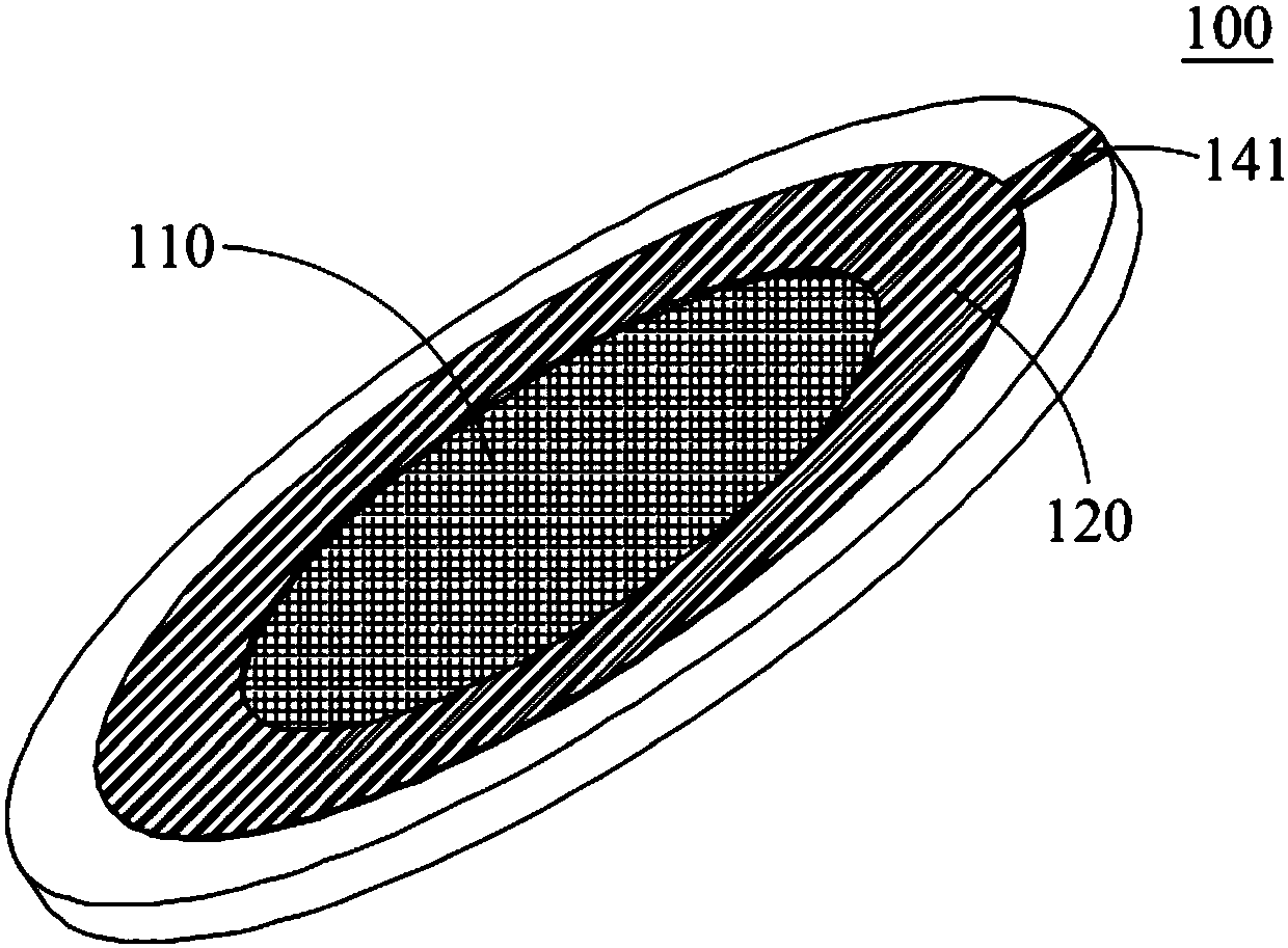
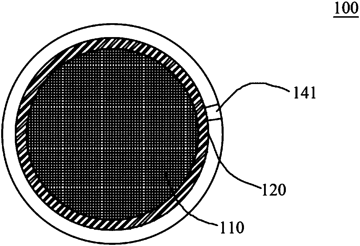
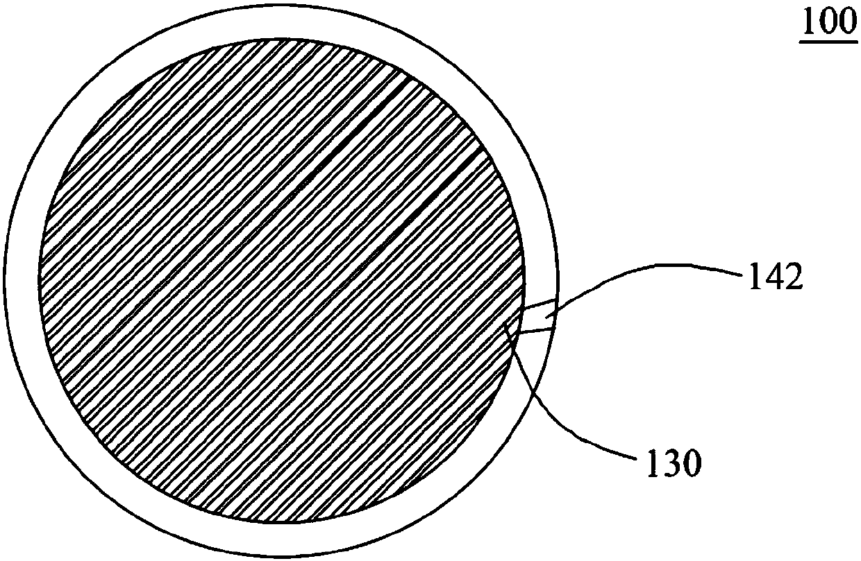
The application discloses an optical device for detecting an optical diffractive element based on mutual capacitance. The optical device comprises the optical diffractive element, a first capacitor electrode, a second capacitor electrode and a detection circuit, wherein the first capacitor electrode is located at one side of the optical diffractive element, the second capacitor electrode and the first capacitor electrode are located oppositely on the other side of the optical diffractive element, and the detection circuit is electrically connected to the first capacitor electrode and the second capacitor electrode to detect the mutual capacitance between the first capacitor electrode and the second capacitor electrode.

Description

technical field [0001] The present application relates to an optical device for detecting an optical diffraction element based on mutual capacitance, and more particularly, to an optical device capable of judging the integrity of an optical diffraction element by detecting a change in capacitance between a pair of electrodes disposed on the optical diffraction element. Background technique [0002] With the improvement of structured light technology, depth cameras using structured light have gradually been applied to various mobile terminals. For example, IphoneX uses depth cameras for face recognition. A general depth camera includes a structured light projection device and a receiving device, and the light source corresponding to the projection device generally adopts infrared light, which is invisible light, that is, the human eye cannot recognize the existence of infrared light. When the infrared light is too strong, it is easy to cause damage to the human eye, so when u...

Claims


Application Information

Patent Timeline
IPC IPC(8): G02B27/42G01D5/24
CPCG02B27/4205G01D5/24
Inventor 陈振宇陈飞帆戎琦黄乾友刘筱迪
Owner NINGBO SUNNY OPOTECH CO LTD
Why Eureka
Try Eureka