
Intelligent mechanical rack used for being coordinated with motion assisting lower limb exoskeleton to adjust human body positions and control method of intelligent mechanical rack

A technology of intelligent machinery and exoskeleton, applied in the direction of manipulators, passive exercise equipment, program-controlled manipulators, etc., can solve problems such as difficult to adjust the body posture in time and accurately, and achieve better training effect, low price and simple structure.

Pending Publication Date: 2019-08-16
ZHEJIANG UNIV CITY COLLEGE
View PDF5 Cites 2 Cited by
  • Summary
  • Abstract
  • Description
  • Claims
  • Application Information

AI Technical Summary

Problems solved by technology

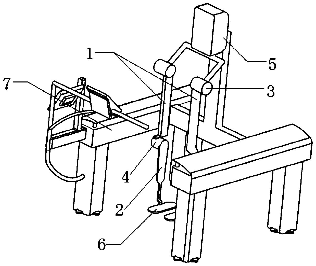
[0003] In view of the above deficiencies, the present invention provides an intelligent mechanical frame and its control method for adjusting the position of the human body in cooperation with the motion-assisted lower limb exoskeleton, which solves the problem that it is difficult to adjust the body posture in time and accurately during the exercise rehabilitation training process

Method used


Image

  • Intelligent mechanical rack used for being coordinated with motion assisting lower limb exoskeleton to adjust human body positions and control method of intelligent mechanical rack
  • Intelligent mechanical rack used for being coordinated with motion assisting lower limb exoskeleton to adjust human body positions and control method of intelligent mechanical rack
  • Intelligent mechanical rack used for being coordinated with motion assisting lower limb exoskeleton to adjust human body positions and control method of intelligent mechanical rack

Examples


Embodiment Construction

[0053] Reference will now be made in detail to the exemplary embodiments, examples of which are illustrated in the accompanying drawings. In the following descriptions and drawings, unless otherwise indicated, the same numerals in different drawings indicate the same or similar elements. The implementations described in the following exemplary examples do not represent all implementations consistent with the present invention. Rather, they are merely examples of arrangements consistent with aspects of the invention as recited in the appended claims. Each embodiment in this specification is described in a progressive manner.

[0054] It should be noted that all directional indications (such as up, down, left, right, front, back...) in the embodiments of the present invention are only used to explain the relationship between the components in a certain posture (as shown in the accompanying drawings). Relative positional relationship, movement conditions, etc., if the specific ...


PUM


Abstract

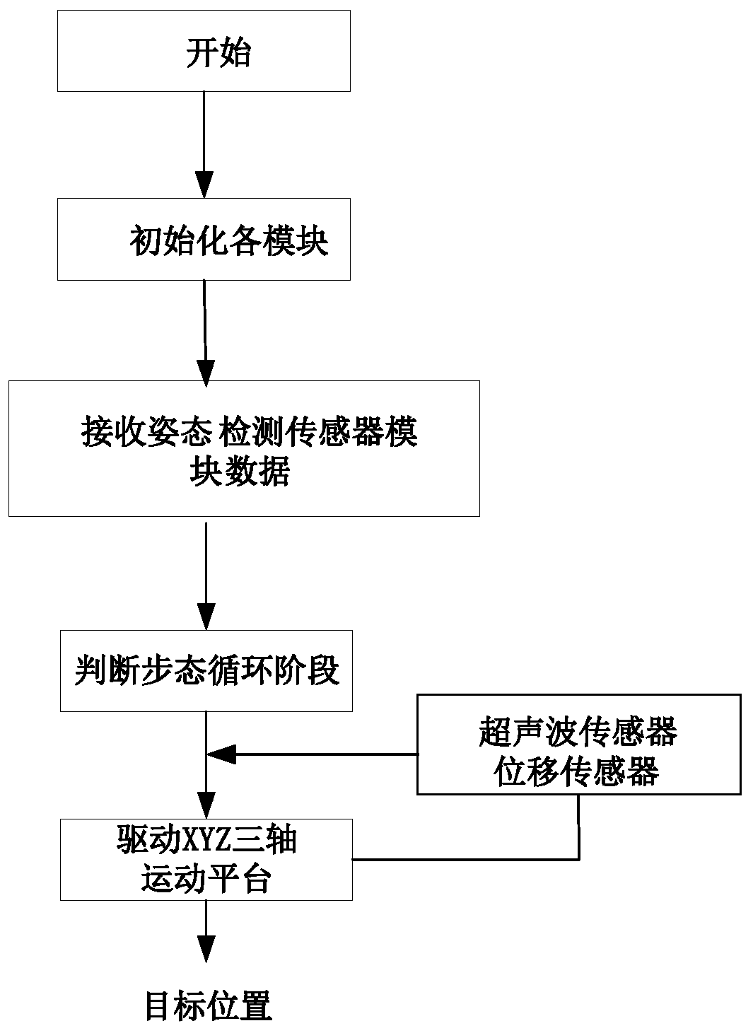
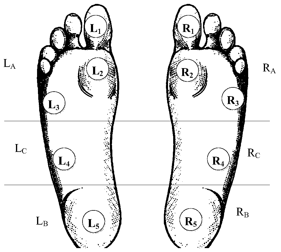
The invention discloses an intelligent mechanical rack used for being coordinated with a motion assisting lower limb exoskeleton to adjust human body positions and a control method of the intelligentmechanical rack. The intelligent mechanical rack comprises a three-axis motion platform, a posture detection sensor module and a single-chip microcomputer module and is characterized in that the three-axis motion platform comprises an X axis, a Y axis and a Z axis; the posture detection sensor module comprises left foot sole pressure detecting module and a right foot sole pressure detecting modulewhich are used for detecting the treading force of a wearer; a mechanical rack sensor module mainly comprises an ultrasonic sensor, a first displacement sensor and a second displacement sensor, the ultrasonic sensor is used for acquiring the height change data, along the Z axis direction, of the gravity center of the wearer, the first displacement sensor is used for measuring the displacement, along the X axis direction, of the gravity center of the wearer, and the second displacement sensor is used for measuring the displacement, along the Y axis direction, of the gravity center of the wearer; the data of the sensors is transmitted to the single-chip microcomputer module, and the three-axis motion platform is controlled by the single-chip microcomputer module. The intelligent mechanicalrack has the advantages that the burden of a patient when the patient wears the exoskeleton is relieved greatly, and the patient can have enough space to wear the exoskeleton.

Description

technical field [0001] The invention mainly relates to the field of exoskeleton robots and the like, and in particular to an intelligent mechanical frame and a control method thereof for adjusting the position of a human body in cooperation with a motion-assisted lower limb exoskeleton. Background technique [0002] Multi-sensor acquisition of information can improve the reliability of system data and improve the accuracy of information. The exoskeleton robot used with the intelligent mechanical frame is equipped with a variety of sensors, which can more accurately detect the walking state of the human body, and the use of the mechanical frame improves the safety and comfort of the exoskeleton. At present, most exoskeletons are used with auxiliary support structures to maintain safety and stability, but the current auxiliary support structures basically use the top rope pull structure, which is poor in comfort and stability, and cannot be adjusted automatically in real time....

Claims


Application Information

Patent Timeline
Patent Type & Authority Applications(China)
IPC IPC(8): A61B5/103A61B5/11A61H1/02A61H3/00B25J9/00B25J9/16B25J19/02
CPCA61B5/1038A61B5/112A61B5/6807A61H1/0262A61H3/00B25J9/0006B25J9/1633B25J19/02A61H2003/005A61H2201/1207A61H2201/1642A61H2201/165A61H2205/108A61H2201/1659A61H2003/007A61H2230/625
Inventor 潘树文李媛媛李威燃严建伟马徐峰
Owner ZHEJIANG UNIV CITY COLLEGE
Learn More