Rotary table with automatic limiting device

An automatic limit and turntable technology, applied in worktables, manufacturing tools, etc., can solve the problem that the limiter cannot meet the requirements of the turntable, and achieve the effects of novel design, convenient system use, and improved reliability and safety.

Active Publication Date: 2019-08-16
CHINA ELECTRONIC TECH GRP CORP NO 38 RES INST
View PDF6 Cites 3 Cited by
  • Summary
  • Abstract
  • Description
  • Claims
  • Application Information

AI Technical Summary

Problems solved by technology

[0004] The technical problem to be solved by the present invention is: how to solve the problem that the existing limit device cannot meet the requirements of the turntable

Method used


Image

  • Rotary table with automatic limiting device
  • Rotary table with automatic limiting device
  • Rotary table with automatic limiting device

Examples


Embodiment 1

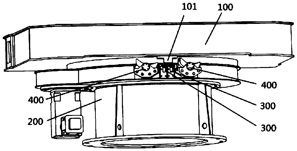
[0031] Such as figure 1 As shown, this embodiment is a turntable with an automatic limit device, and the turntable includes a turntable 100, a base 200, a proximity switch 300 and a limit member 400;

[0032] The turntable 100 is rotatably connected to the base 200, the bottom surface of the turntable 100 is provided with a moving block 101, and the base is provided with a limit mechanism capable of limiting the rotation of the move block 101, and the limit mechanism includes a proximity switch 300 and a limit piece 400, the limit mechanism that can limit the movement of the stopper 101 is set at the final limit position, along the direction of rotation, the proximity switch 300 is set in front of the limit piece 400, the proximity switch 300 is connected to the controller, and the controller is connected to The motor that controls the rotation of the turntable.

[0033] Such as figure 2 , image 3 , the two ends of the limiting member 400 can realize the state that one en...

Embodiment 2

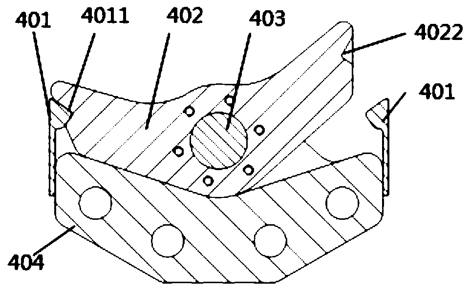
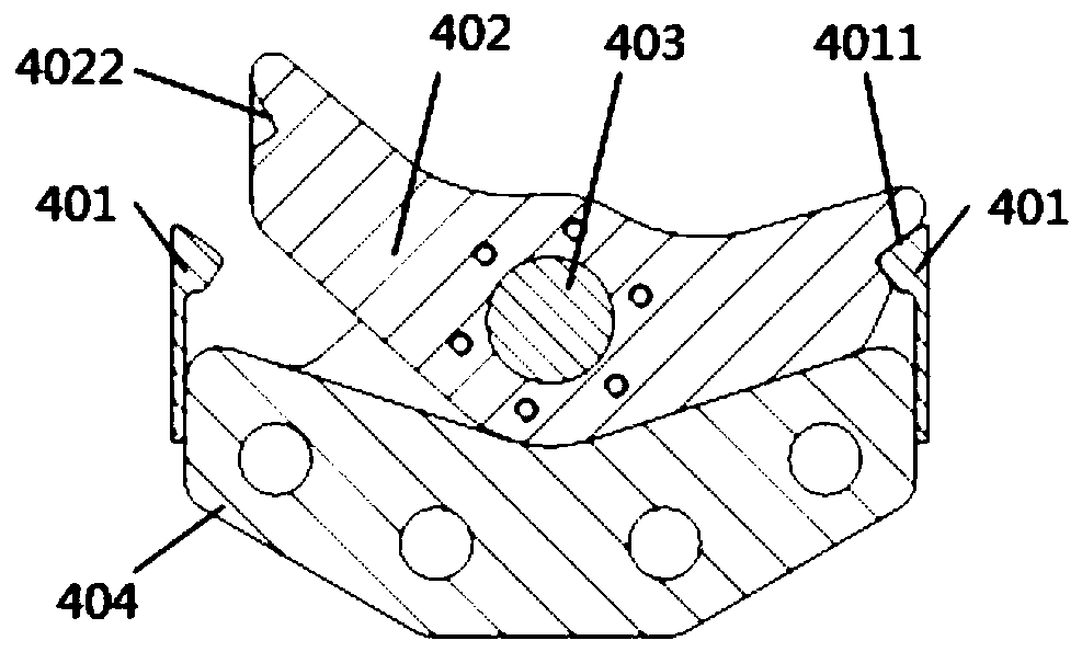
[0036] Such as Figure 4 As shown, on the basis of the first embodiment, the limiting member 400 includes a spring plate 401, a stopper 402, a rotating shaft 403, and a mounting plate 404;

[0037] The mounting plate 404 is installed on the base 200, the block 402 is movably connected with the mounting plate 404 through the pin shaft 403, the spring leaf 401 is vertically installed on both sides of the mounting plate 404, the block 402 is provided with a groove 4022, and the spring leaf 401 is provided with a protrusion 4011 corresponding to the groove 4022, combined with figure 2 , image 3 As shown, when the protrusion 4011 of the spring sheet 401 on one side is snapped into the groove 4022, the protrusion 4011 of the spring sheet 401 on the other side is not snapped into the groove 4022, and the protrusion 4011 is snapped into the groove 4022. One side is lower than the side where the protrusion 4011 is not inserted into the groove 4022, so that under no external force, ...


PUM


Abstract

The invention discloses a rotary table with an automatic limiting device. The rotary table comprises a rotary plate and a base; the rotary plate is rotationally connected with the base; the bottom surface of the rotary plate is provided with a movable stop dog; the base is provided with a limiting mechanism capable of limiting rotation of the movable stop dog; the limiting mechanism comprises a proximity switch and a limiting member; in the rotating direction, the proximity switch is arranged in front of the limiting member, the proximity switch is connected with a controller, and the controller is connected with a motor for controlling the rotary plate to rotate; the limiting member is provided with two stations, the first end of the first station is high, and the second end of the firststation is low; the first end of the second station is low, and the second end of the second station is high; and the movable stop dog can be limited from the lower end to the higher end through the limiting member. The rotary table has the beneficial effects that through redundant design of double protection of the limiting mechanism and the proximity switch, mechanical limiting can be adopted when the proximity switch fails, and thus the reliability and safety of rotation limiting are improved.

Description

technical field [0001] The invention relates to a turntable, in particular to a turntable capable of automatic positioning. Background technique [0002] With the development of technology and equipment manufacturing capabilities, the application of turntables is becoming more and more extensive. The rotation of the turntable is divided into continuous rotation and rotation with limited rotation angle range. For the turntable that rotates within a limited range of movement angle, a limit device must be equipped to prevent the turntable from continuing to move, so that the turntable can be protected from damage; when the turntable rotation range is less than ±180°, the entire movement stroke of the turntable is less than one cycle, and the turntable moves to the limit position. There is still enough space to install the mechanical limit device; when the rotary range of the turntable is greater than ±180°, the rotary stroke of the turntable exceeds one circle, and there is no...

Claims


Application Information

Patent Timeline
Patent Type & Authority Applications(China)
IPC IPC(8): B25H1/02B25H1/14
CPCB25H1/02B25H1/14
Inventor 郭向东房景仕李付军郭亚军何文杰陶国灿
Owner CHINA ELECTRONIC TECH GRP CORP NO 38 RES INST
Why Eureka
Try Eureka