Floating type anti-icing structure of ocean structure and installation method of floating type anti-icing structure

A marine structure and installation method technology, applied in the field of marine engineering, can solve the problems of affecting the fatigue life of the main body of the marine structure, increasing the wave load of the marine structure, and the large volume and weight of the ice-resistant structure, so as to reduce the marine operation process, The installation process is convenient and the structure is simple

Pending Publication Date: 2019-08-16
SHANGHAI INVESTIGATION DESIGN & RES INST
View PDF0 Cites 2 Cited by
  • Summary
  • Abstract
  • Description
  • Claims
  • Application Information

AI Technical Summary

Problems solved by technology

The traditional anti-icing structure is usually an upper and lower cone structure fixed on the main body of the marine structure. This structure needs to cover the range of tide level fluctuations in the whole winter. Due to the large change of the ocean tide level, the volume and weight of the anti-icing structure are often relatively large. Large, and often need to be welded at sea, it is inconvenient to install
Therefore, the traditional anti-ice structure has the following problems: first, the economy is poor; second, in the non-freezing period, the huge anti-ice structure will increase the overall wave load of the marine structure; The main body is rigidly fixed, so that the ice-induced vibration will seriously affect the fatigue life of the main body of the marine structure

Method used


Image

  • Floating type anti-icing structure of ocean structure and installation method of floating type anti-icing structure
  • Floating type anti-icing structure of ocean structure and installation method of floating type anti-icing structure
  • Floating type anti-icing structure of ocean structure and installation method of floating type anti-icing structure

Examples


Embodiment Construction

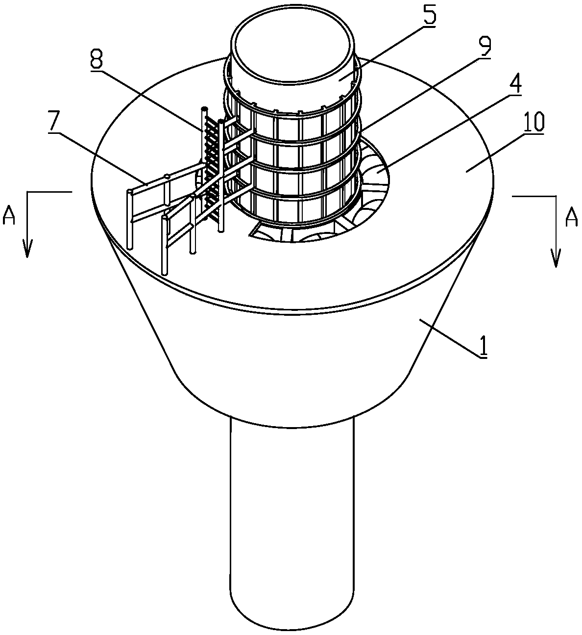
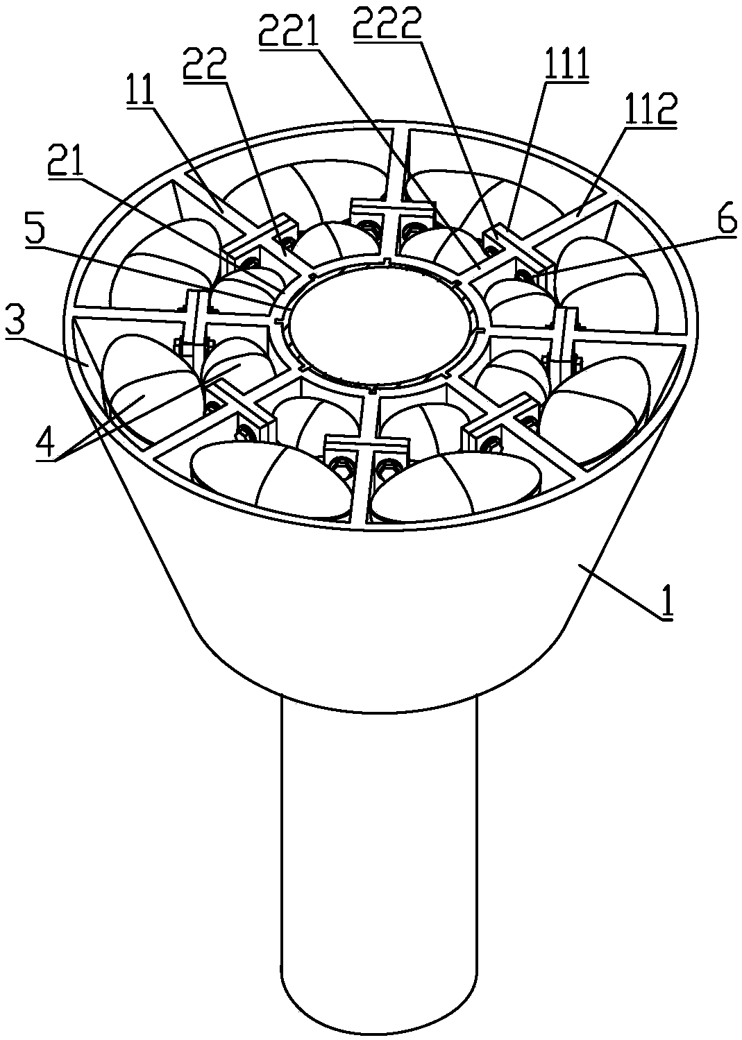
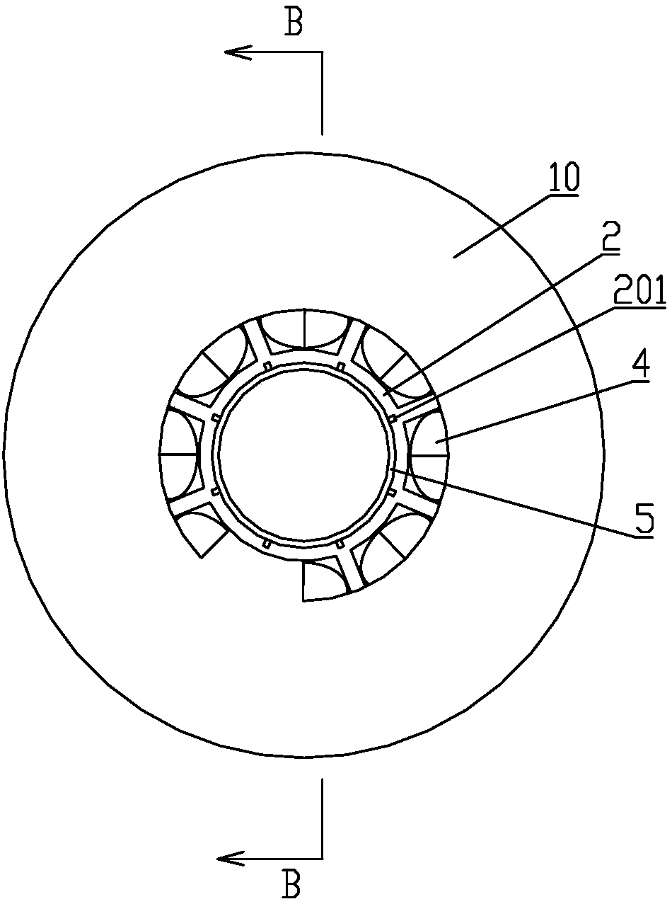
[0035] The specific implementation manners of the present invention will be described in further detail below in conjunction with the accompanying drawings. These embodiments are only used to illustrate the present invention, not to limit the present invention.

[0036] In the description of the present invention, it should be noted that the terms "center", "longitudinal", "transverse", "upper", "lower", "front", "rear", "left", "right", " The orientations or positional relationships indicated by "vertical", "horizontal", "top", "bottom", "inner", "outer", etc. are based on the orientation or positional relationships shown in the drawings, and are only for the convenience of describing the present invention and simplifying Describes, but does not indicate or imply that the device or element referred to must have a specific orientation, be constructed in a specific orientation, and operate in a specific orientation, and therefore should not be construed as limiting the inventio...


PUM


Abstract

The invention relates to the technical field of marine engineering, in particular to a floating type anti-icing structure of an ocean structure and an installation method of the floating type anti-icing structure. The floating type anti-icing structure comprises an axially hollow icebreaking shell, a damping component is arranged in the icebreaking shell, a plurality of containing spaces are formed between the damping component and the icebreaking shell, at least one floating body is arranged in each containing space, and the icebreaking shell is arranged on a supporting pile of the ocean structure in a sleeving mode through the damping component and can move in the axial direction. The installation method comprises the steps that first, the icebreaking shell, the damping component and thesupporting pile are prefabricated on the land, and the damping component is installed on the icebreaking shell; second, the supporting pile is driven into a seabed target position; third, the floating bodies are arranged between the inner part of the icebreaking shell and the damping component; fourth, the damping component is installed on the supporting pile; and fifth, the buoyancy of the floating bodies is adjusted, so that the icebreaking shell floats on the sea surface. The floating type anti-icing structure is convenient to install, and can lower the ice force and the ice-induced vibration borne by an ocean structure body.

Description

technical field [0001] The invention relates to the technical field of marine engineering, in particular to a floating anti-icing structure of a marine structure and an installation method of the floating anti-icing structure. Background technique [0002] With the development of marine structures in ice areas, it is found that sea ice directly acts on the main body of marine structures, which is very harmful to them, so it is necessary to set up anti-ice structures. The traditional anti-icing structure is usually an upper and lower cone structure fixed on the main body of the marine structure. This structure needs to cover the range of tide level fluctuations in the whole winter. Due to the large change of the ocean tide level, the volume and weight of the anti-icing structure are often relatively large. It is large, and often needs to be welded at sea, which is inconvenient to install. Therefore, the traditional anti-ice structure has the following problems: first, the ec...

Claims


Application Information

Patent Timeline
Patent Type & Authority Applications(China)
IPC IPC(8): E02B17/00
CPCE02B17/0021E02B17/003
Inventor 黄俊
Owner SHANGHAI INVESTIGATION DESIGN & RES INST
Why Eureka
Try Eureka