Intelligent water energy cycle power saving system

A water energy and intelligent technology, applied in water supply pipeline system, hydroelectric power generation, industrial water supply saving, etc., can solve the problems of reduced energy consumption of circulating water, unsatisfactory power saving effect, surplus actual flow, etc., to reduce power consumption, reduce The effect of manual management cost and reducing manual misoperation

Active Publication Date: 2021-06-04
杨广平
View PDF10 Cites 0 Cited by
  • Summary
  • Abstract
  • Description
  • Claims
  • Application Information

AI Technical Summary

Problems solved by technology

Third, in order to ensure that the water supply flow meets the maximum needs of users, the designer must design the water supply pump according to the maximum required flow, and consider the safety factor. Therefore, the actual flow of the pump has a large margin
Fourth, due to changes in ambient temperature and user needs, there is a surplus in actual traffic
The shaft extension tubular turbine converts the residual pressure of the system into kinetic energy and directly provides it to the high-efficiency water pump, replacing or reducing the power consumption of the motor, thereby reducing the energy consumption of circulating water. This technology is only applicable to those with low return water pressure and small return water energy. Circulating water system, its use range is not wide, and the power saving effect is not ideal
And it is troublesome to use the operation management

Method used


Image

  • Intelligent water energy cycle power saving system
  • Intelligent water energy cycle power saving system
  • Intelligent water energy cycle power saving system

Examples


Embodiment 1

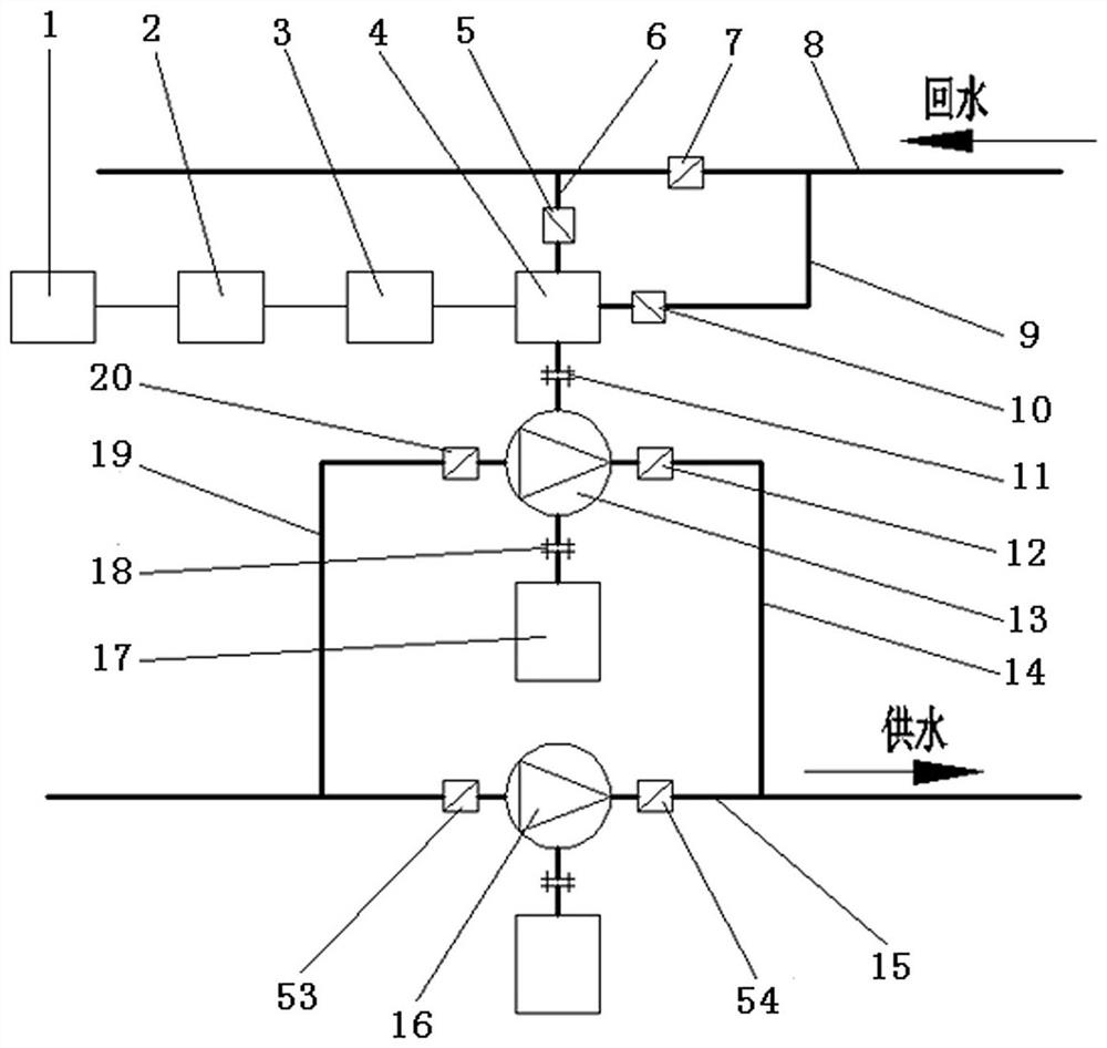
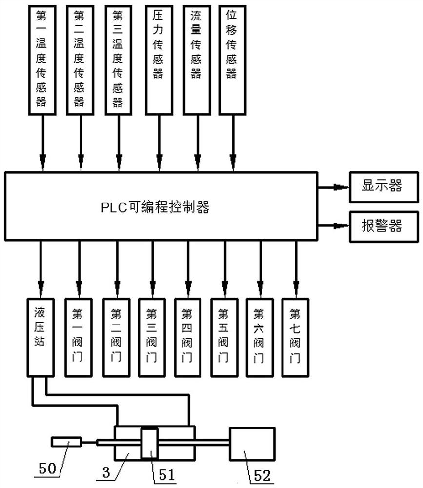
[0023] figure 1 It is to add a set of intelligent water energy circulation and power saving system to the usual water pump circulation water supply system. The intelligent water energy cycle power-saving system consists of an intelligent control device, a hydraulic turbine bypass, and a high-efficiency water pump bypass. The turbine bypass is composed of a Francis turbine 4 , a first water inlet pipeline 9 , a first valve 10 , a first water outlet pipeline 6 and a second valve 5 . The intelligent control device is composed of several sensors, an intelligent control cabinet 1, a hydraulic station 2 and a servomotor 3. The high-efficiency water pump bypass is composed of a high-efficiency water pump 13, a second water inlet pipeline 19, a third valve 20, a second water outlet pipeline 14, a fourth valve 12, and an asynchronous motor 17.

[0024] One end shaft of the high-efficiency water pump 13 is connected to the shaft of the water turbine 4 through the first coupling 11, an...

Embodiment 2

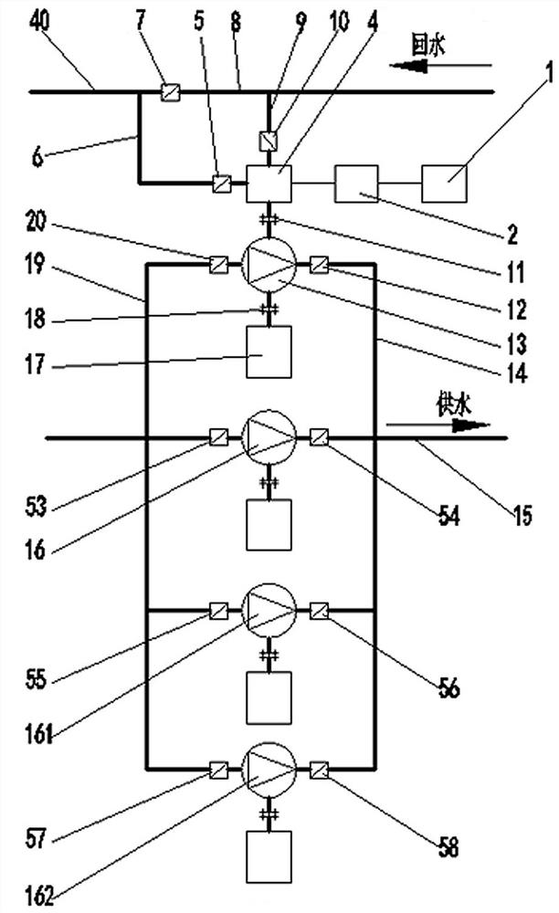
[0035] Add a set of intelligent water energy cycle power saving system to the usual multi-pump circulating water supply system, such as image 3 It is a common water supply system with dual-use and one-standby or one-use and two-standby. The intelligent water energy cycle power-saving system consists of an intelligent control device, a hydraulic turbine bypass, and a high-efficiency water pump bypass. The hydraulic turbine bypass is composed of a hydraulic turbine 4 , a first water inlet pipeline 9 , a first valve 10 , a first water outlet pipeline 6 and a second valve 5 . In the water supply system with low return water pressure, the water turbine 4 is suitable to adopt the rear shaft extension through-flow paddle type water turbine. The intelligent control device is composed of several sensors, an intelligent control cabinet 1 and a hydraulic station 2. The high-efficiency water pump bypass is composed of a high-efficiency water pump 13, a second water inlet pipeline 19, a...


PUM


Abstract

The invention is an intelligent water energy cycle power-saving system, which solves the problems that the traditional system has no power generation function, inconvenient maintenance and operation management, and high energy consumption. It consists of an intelligent control device, a turbine bypass, and a high-efficiency water pump bypass. The first temperature sensor, pressure sensor and flow sensor are installed on the return water pipeline, the second temperature sensor is installed on the water supply pipeline, and the third sensor is installed on the bearing seat of the turbine. The temperature sensor is installed on the servomotor of the water turbine. The displacement sensor is installed. The sensor collects the relevant parameters of the return water and the water supply pipeline and provides them to the PLC programmable controller of the intelligent control cabinet 1. The programmable controller collects the real-time data of the return water pipeline according to the sensor Changes in temperature, pressure, flow and temperature of the water supply pipeline are compared with the set values ​​of the parameters required by the water supply system. When one of these parameters exceeds the set value, the programmable controller adjusts the water turbine through the hydraulic station and the servomotor The flow rate and the flow rate of the water pump in the water supply pipeline make this parameter return to the set value range.

Description

technical field [0001] The invention is related to the energy saving of the pump water supply system. Background technique [0002] Many pump water supply systems currently use one or several water pumps to pressurize the water and deliver it to the required scene. There are many ways to deal with the used water flow. Some lead the water to the water treatment equipment and then discharge it to the river; some discharge it underground; recycle. However, the water flow after use often also has a large amount of water energy: first, there is still surplus potential energy. For example, the ground source heat pump takes water from the ground to the ground and then flows into the potential energy of the ground. The equipment or materials in the factory need to be cooled by the heat exchanger. Because the process requires a higher installation position, the cooling water flows from the high-level heat exchanger to the hot water pool or into the cooling tower, and there is stil...

Claims


Application Information

Patent Timeline
Patent Type & Authority Patents(China)
IPC IPC(8): E03B1/02E03B7/07F03B13/00F03B15/12
CPCE03B1/02E03B7/07F03B13/00F03B15/12Y02E10/20Y02A20/30
Inventor 杨广平杨智焜
Owner 杨广平
Why Eureka
Try Eureka