

Method for determining an oil-increasing effect of carbonate reservoir plugging agent deep profile control and flooding technology
A carbonate rock reservoir and determination method technology, which is applied in the field of water injection, development and flood control in oilfields, can solve problems such as changes in oil increase in well groups, increase in water flood control, etc., and achieves the effect of promoting popularization and application.
Active Publication Date: 2019-08-16
CHINA OILFIELD SERVICES +1
View PDF9 Cites 2 Cited by
- Summary
- Abstract
- Description
- Claims
- Application Information
AI Technical Summary
Problems solved by technology
[0005] The purpose of the present invention is to overcome the deficiencies of the prior art, and use fluid seepage mechanics to establish a set of plugging agent regulation and displacement seepage model and effect dynamic prediction method, and use dynamic data such as on-site injection pressure and water injection volume to
Method used
View moreImage
Smart ImageViewing Examples

Examples
 PUM
 Abstract
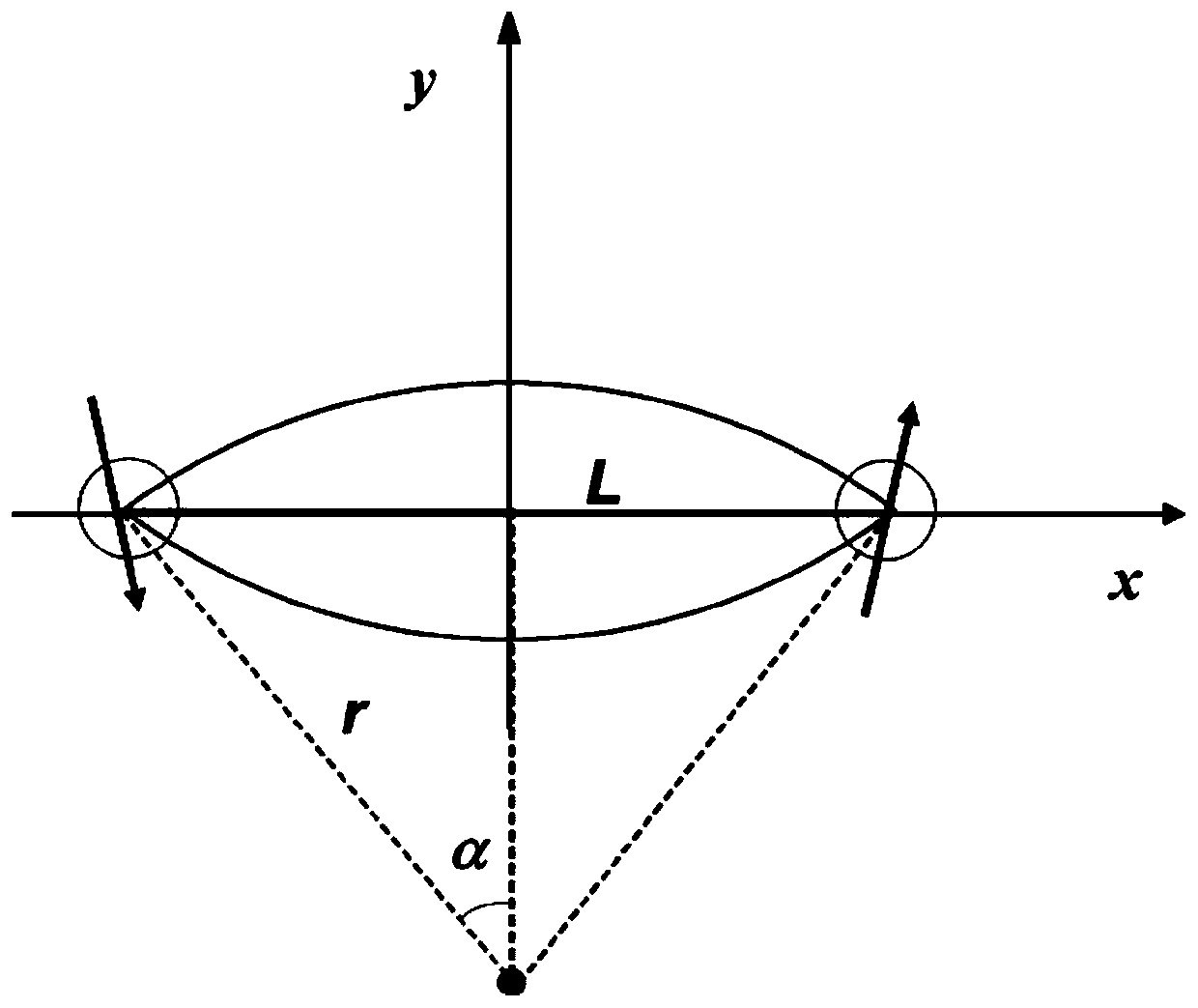
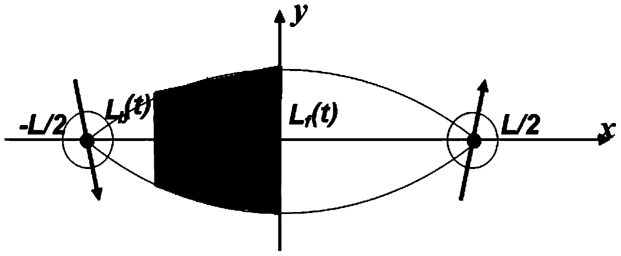
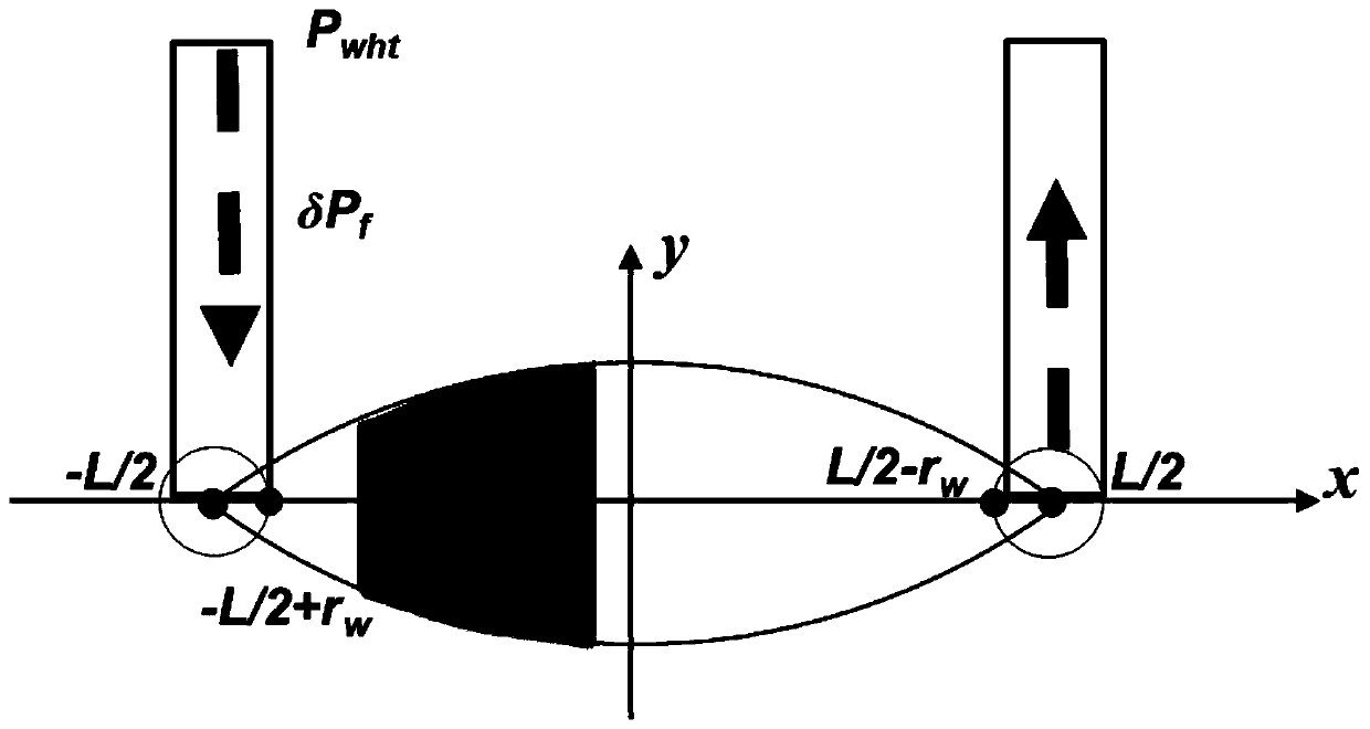
The invention relates to a method for determining an oil-increasing effect of carbonate reservoir plugging agent deep profile control and flooding technology. The method includes the steps that steps1, a plugging agent profile control and flooding physical model is established according to the fluid seepage between injection wells and oil production wells being equivalent to the flow in a flow pipe; step 2, according to the plugging agent profile control and flooding physical model, the position of the plugging agent leading edge and the position of a plugging agent tail skirt and the movement track of plugging agent slug in porous media, a plugging agent seepage mathematical model is established; step 3, according to the plugging agent seepage mathematical model and the process of plugging agent injection, the flow rate and injection pressure in the process of profile control and flooding are determined; and step 4, according to the number of effective oil production wells controlledby the injection wells, the change of water cut of oil wells, the plugging agent seepage mathematical model in the second and third steps and the profile control and flooding flow rate and pressure,the oil increment and recovery efficiency of oilfield blocks are determined after the profile control and flooding measures are taken. The method is accurate, reliable and high in practicality.
Description
technical field [0001] The invention belongs to the technical field of oilfield water injection development control and displacement technology, and relates to the seepage research of plugging agent, in particular to a method for determining the oil-increasing effect of the deep control and displacement technology of plugging agent in carbonate rock reservoirs. Background technique [0002] The storage space of carbonate reservoirs is dominated by caves, followed by fractures and dissolved pores. Fractures are the main seepage channels for formation fluid, and the fluid flow in the porous medium of the reservoir is similar to pipe flow. At the same time, due to the long-term scouring effect of injected water, the cemented structure of rock particles in the reservoir is easily destroyed, forming a structure similar to "big pores". As the production enters the middle and later stages, the injected water rushes along the dominant channel of the reservoir, causing the water cut...
Claims
Login to View More Application Information
Patent Timeline
 IPC IPC(8): E21B43/22E21B49/00
CPCE21B43/16E21B49/00
Inventor冯青杨浩黄子俊杨静李成勇李啸南曾鸣商永涛
OwnerCHINA OILFIELD SERVICES