Impeller double-row slotting plunge milling complementary machining method

A processing method, plunge milling technology, applied in metal processing, metal processing equipment, metal processing machinery parts, etc., can solve the problems that restrict the efficiency of double row slotting plunge milling, excessive material residue, complex geometric features, etc. Achieve significant social and economic benefits, promote popularization and application, and implement simple effects

Active Publication Date: 2022-03-11
DALIAN UNIV OF TECH
View PDF8 Cites 0 Cited by
  • Summary
  • Abstract
  • Description
  • Claims
  • Application Information

AI Technical Summary

Problems solved by technology

The double-row slotting and milling process of the impeller is still in the actual verification stage, and the application effect is better for the impeller flow channel with a large blade curvature. For the impeller flow channel with a small blade curvature, in order to ensure the uniformity of the rough machining allowance of the blade , the tool axis vector changes drastically, and there are too many material residues between the two-row plunging milling tool paths, and the geometric features are complex, which brings great difficulties to the subsequent semi-finishing and seriously restricts the double-row slotting and plunging milling. Processing efficiency advantage

Method used


Image

  • Impeller double-row slotting plunge milling complementary machining method
  • Impeller double-row slotting plunge milling complementary machining method
  • Impeller double-row slotting plunge milling complementary machining method

Examples


Embodiment 1

[0060] Such as Figure 1-3 As shown, the present invention provides an impeller double-row slotting insert milling repair method, specifically as follows.

specific Embodiment approach

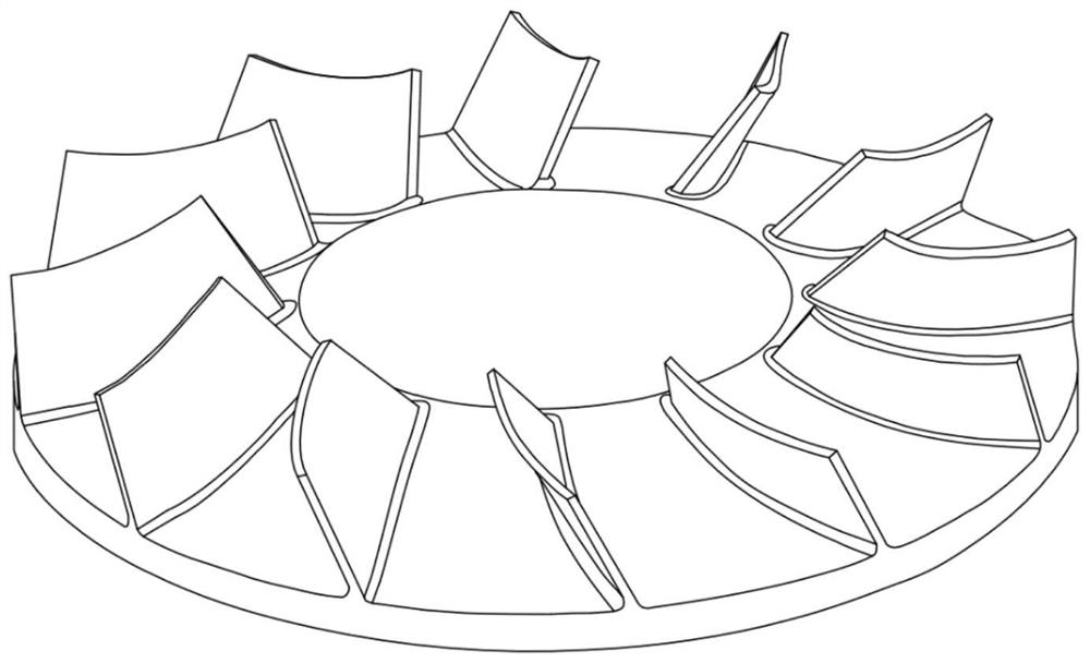
[0061] Conditions of this embodiment: the CAD model of the known semi-open integral impeller, the diameter of the impeller is 600mm, such as figure 1 shown. The specific implementation is as follows:

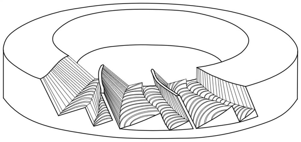
[0062] (1) Analyze the geometry of the semi-open integral impeller flow channel, formulate a double-row slotting and milling process plan, and perform rough machining on the impeller flow channel, such as figure 2 .

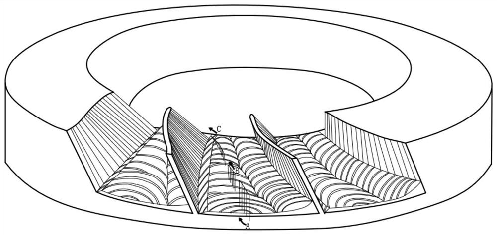
[0063] (2) Establish the material residual geometric model between the two tool paths after the double-row slotting milling process, divide the flow channel into three sections A, B and C, and combine the residual height geometry, the curvature of the impeller hub surface and the common tool size Sequence, respectively select plunge milling tools with diameters of 80mm, 50mm and 30mm. And plan the tool trajectory for plunging and milling.

[0064] (3) Use the linear interpolation command to plan the coordinates of the sequence point coordinates and the directi...


PUM

PropertyMeasurementUnit
Diameteraaaaaaaaaa

Abstract

The invention provides an impeller double-row slotting plunge milling complementary machining method, and belongs to the field of machining and tools. The method comprises the following steps: constructing a semi-open type integral impeller model; rough machining is conducted on the impeller runner; a material residual geometric model between two tool paths after double-row slotting plunge milling is established, and a plunge milling complementary machining tool is selected; planning the path of a plunge milling supplementary machining tool, and carrying out plunge milling supplementary machining to remove residual materials after double-row slotting plunge milling machining; according to the material residue condition between tool paths after double-row slotting plunge milling supplementary machining, whether second plunge milling supplementary machining is carried out or not is judged; and tool path information is converted into a machining program, and a machine tool is driven to complete impeller passage double-row slotting plunge milling complementary machining. According to the double-row slotting plunge milling method, an existing double-row slotting plunge milling technology is supplemented and improved, and the machining efficiency can be further improved by about 20%; the method is easy to implement, application of the plunge milling technology in impeller machining is promoted, and remarkable social and economic benefits are achieved.

Description

technical field [0001] The invention relates to the technical field of mechanical processing and tools, in particular, to a method for inserting and milling supplementary double-row slotting of an impeller. Background technique [0002] Centrifugal compressors are widely used in aerospace, petrochemical, natural gas, automobile and other industries, and are a typical core equipment of basic industries. The semi-open impeller is the core component of the centrifugal compressor, and its processing technology will directly affect the processing efficiency and production cost. It has always been a research hotspot and a competitive weapon for scientific research institutes and enterprises. [0003] With the increasing diversification of impeller applications, the requirements for the service life and working efficiency of the impeller are getting higher and higher. Through an original blank, machining represented by CNC machine tools is currently the mainstream method for high-...

Claims


Application Information

Patent Timeline
IPC IPC(8): B23C3/28B23C9/00B23Q15/22
CPCB23C3/28B23C9/00B23Q15/22
Inventor 郭明龙魏兆成舒鑫雍建华王敏杰王学勤
Owner DALIAN UNIV OF TECH
Why Eureka
Try Eureka