Speed bump power generation device and working method

A technology for power generation devices and speed bumps, applied in electromechanical devices, electric components, electrical components, etc., can solve problems such as loss of kinetic energy and energy waste in automobiles, and achieve the effects of avoiding waste, being easy to manufacture, and improving comfort.

Inactive Publication Date: 2019-08-16
QINGDAO TECHNOLOGICAL UNIVERSITY
View PDF0 Cites 0 Cited by
  • Summary
  • Abstract
  • Description
  • Claims
  • Application Information

AI Technical Summary

Problems solved by technology

The inventor found that the use of speed bumps also causes the car to lose part of its kinetic energy, so that this part of energy is wasted

Method used


Image

  • Speed bump power generation device and working method
  • Speed bump power generation device and working method
  • Speed bump power generation device and working method

Examples


Embodiment 2

[0044] This embodiment discloses a working method of a deceleration belt power generation device:

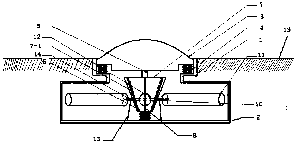
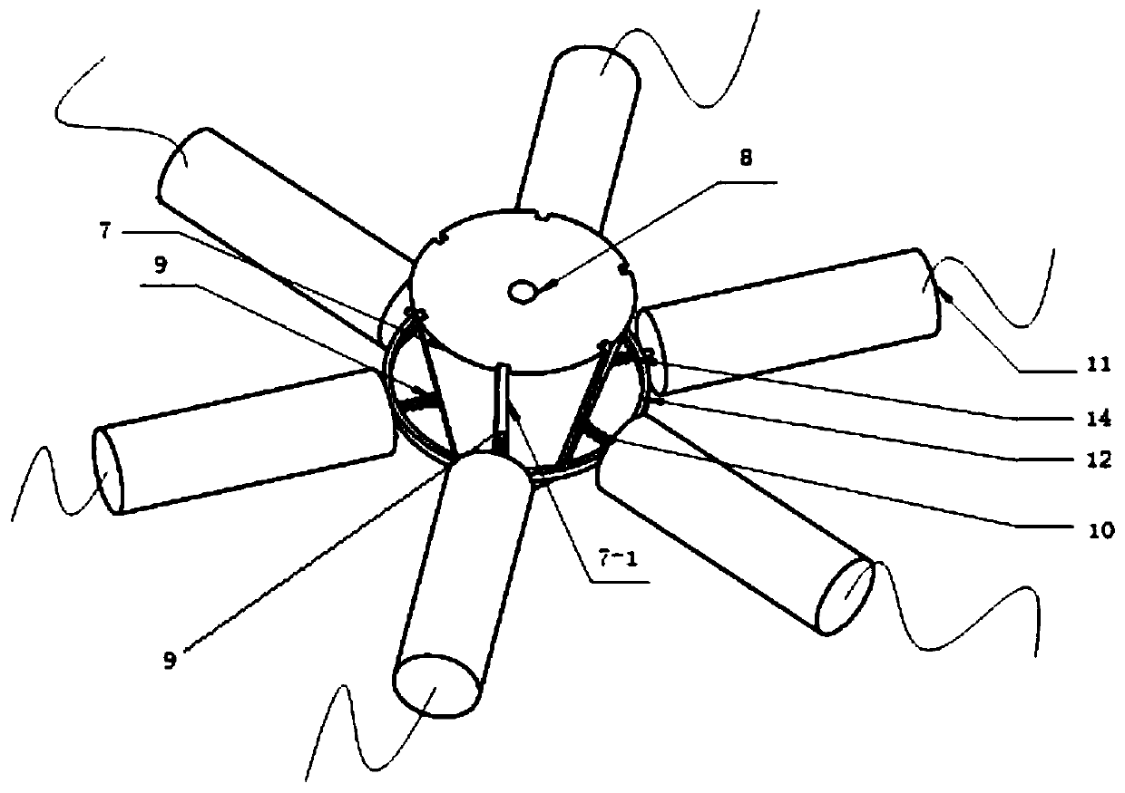
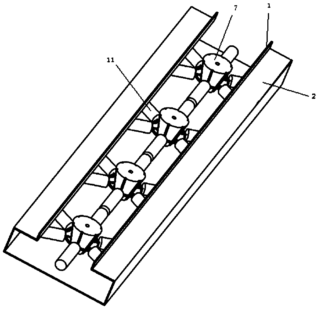
[0045] The casing is buried 15 below the ground, and the top surface of the casing is flush with the ground. When the vehicle is running against the speed bump, the speed bump moves downward under the action of the vehicle pressure, and the inverted conical frustum moves downward synchronously. Contacting the side of the inverted cone, the downward movement of the inverted cone drives the transmission rod to move away from the axis of the inverted cone, and the movement of the transmission rod drives the linear generator to generate electricity. When the wheels of the vehicle leave the speed reduction belt, the first spring and Under the action of the second spring, the deceleration belt and the transmission part move upwards and return to their original positions. At the same time, under the action of the third spring, the transmission rod moves toward the axis of the inverted c...


PUM


Abstract

The invention relates to a speed bump power generation device and a working method. The speed bump power generation device comprises a housing buried below the ground, wherein the top of the housing is open, and a speed bump is arranged at the opening; the speed bump is elastically connected with the housing; a transmission element is connected to the bottom surface of the speed bump; the transmission element is elastically connected with the housing; the side surface of the transmission element makes contact with one end of each of a plurality of transmission rods; the other end of each transmission rod penetrates through a guide element and then is connected with a linear power generator fixed into the housing; and each transmission rod is fixedly connected with one end of an elastic element, and the other end of the elastic element is fixedly connected with the guide element. The lifting movement of the transmission element is capable of co-acting with the elastic element to drive the transmission rods to move, and the movement of the transmission rods is capable of driving the linear power generator to generate power; and by using the speed bump power generation device, energywaste is avoided.

Description

technical field [0001] The invention relates to the technical field of power generation equipment, in particular to a speed bump power generation device and a working method. Background technique [0002] In order to ensure the safe driving of motor vehicles and the safety of pedestrians, speed bumps are usually set up on some special road sections to force the driver to slow down to ensure safety. With the continuous increase of vehicles and population, more and more speed bumps are laid on the road. The inventors found that the use of the speed bump also causes the vehicle to lose part of its kinetic energy, thereby causing this part of energy to be wasted. Therefore, collecting and utilizing this part of energy is of great significance to environmental protection, energy saving and emission reduction. Contents of the invention [0003] The purpose of the present invention is to overcome the above-mentioned deficiencies in the prior art, and provide a speed bump power ...

Claims


Application Information

Patent Timeline
Patent Type & Authority Applications(China)
IPC IPC(8): F03G7/00E01F9/529H02K7/18
CPCE01F9/529F03G7/00H02K7/1869
Inventor 刘庆玉周锦辉龚静茹刘红妹侯敏闫志远
Owner QINGDAO TECHNOLOGICAL UNIVERSITY
Why Eureka
Try Eureka