Quick pipe joint and joint assembly

A kind of pipe joint, fast technology, applied in the direction of engine components, engine seals, mechanical equipment, etc., can solve the problems of high use cost, difficult installation and disassembly, etc., to achieve the effect of reduced processing cost, low cost and light weight

Pending Publication Date: 2019-08-16
弗兰科希管件系统(上海)有限公司
View PDF0 Cites 1 Cited by
  • Summary
  • Abstract
  • Description
  • Claims
  • Application Information

AI Technical Summary

Problems solved by technology

[0006] The purpose of the present invention is to provide a quick pipe joint and joint assembly, so as to alleviate the technical problems of difficult installation and disassembly of traditional joints and high cost of use in the prior art

Method used


Image

  • Quick pipe joint and joint assembly
  • Quick pipe joint and joint assembly
  • Quick pipe joint and joint assembly

Examples


Embodiment 1

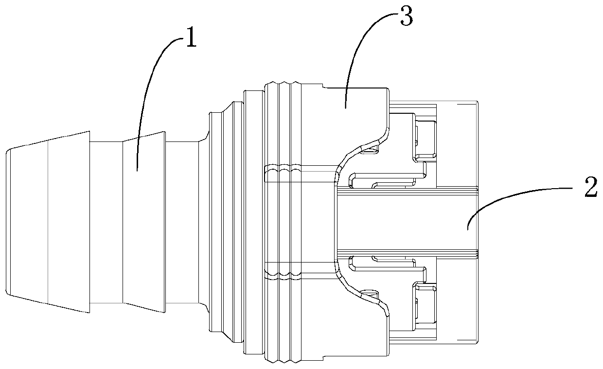
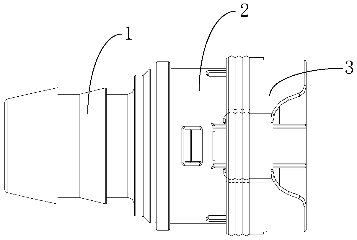
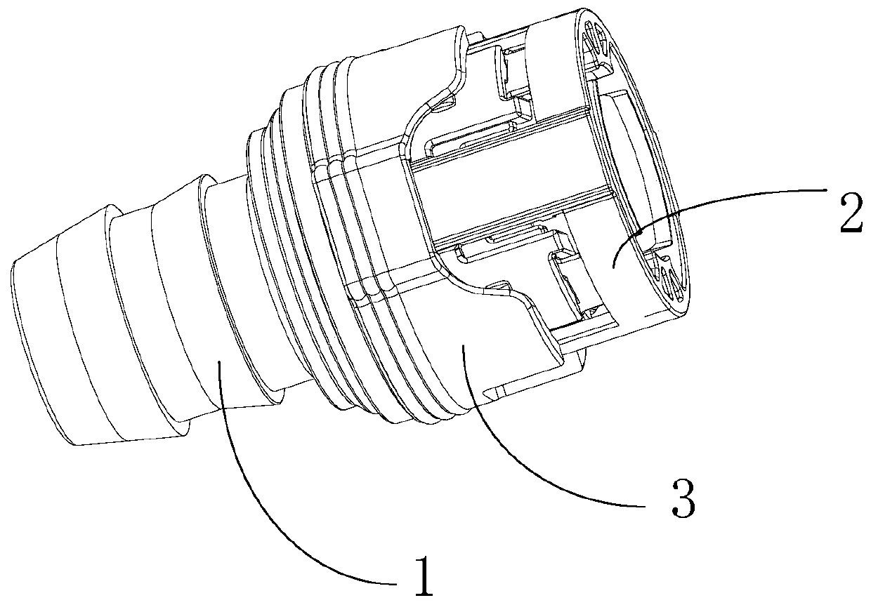
[0043] This embodiment provides a quick fitting, please refer to Figure 1 to Figure 9 , combined with Figure 10 , Figure 11 , and focus on the Figure 4 , the quick pipe joint includes a joint body 1 and an integrated snap sleeve 2; the joint body 1 has a lumen for connecting with the counterpart 0; the integrated snap sleeve 2 includes a snap sleeve 21 and is connected to the The inner guide sleeve 23 of the buckle sleeve 21; the joint body 1 is connected to the buckle sleeve 21 and / or the guide sleeve 23 by inserting one end between the buckle sleeve 21 and the guide sleeve 23; on the inner wall surface of the buckle sleeve 21 There is provided on the upper part a counterpart piece engagement protrusion 211 for clamping with the counterpart piece 0, and the buckle sleeve 21 is made of elastic material.

[0044] Among them, "and / or" means that the joint body 1 is connected to the buckle sleeve 21 by inserting one end between the buckle sleeve 21 and the guide sleeve 23,...

Embodiment 2

[0057] This embodiment provides a joint assembly, refer to Figure 10 and Figure 11 , the joint assembly includes counterpart 0 and quick pipe joint.

[0058] combined reference Figure 1 to Figure 9 , the quick pipe joint includes a joint body 1 and an integrated snap sleeve 2; the joint body 1 has a lumen for connecting with the counterpart 0; the integrated snap sleeve 2 includes a snap sleeve 21 and is connected to the The inner guide sleeve 23 of the buckle sleeve 21; the joint body 1 is connected to the buckle sleeve 21 and / or the guide sleeve 23 by inserting one end between the buckle sleeve 21 and the guide sleeve 23; on the inner wall surface of the buckle sleeve 21 There is provided on the upper part a counterpart piece engagement protrusion 211 for clamping with the counterpart piece 0, and the buckle sleeve 21 is made of elastic material.

[0059] Among them, "and / or" means that the joint body 1 is connected to the buckle sleeve 21 by inserting one end between ...


PUM


Abstract

The invention provides a quick pipe joint and a joint assembly, and relates to the technical field of pipeline connecting pieces. The quick pipe joint comprises a joint body and an integrated clampingsleeve, wherein the joint body is provided with a pipe cavity used for being connected with a opponent piece, and the integrated clamping sleeve comprises a buckle sleeve and a guide sleeve connectedto the interior of the buckle sleeve through a connecting rib; one end of the joint body is inserted between the buckle sleeve and the guide sleeve, so that the joint body is connected with the buckle sleeve and/or the guide sleeve; the inner wall face of the buckle sleeve is provided with a opponent piece clamping bulge used for being clamped with the opponent piece, and the buckle sleeve is made of elastic material; and the joint assembly comprises the opponent piece and the quick pipe joint, and a opponent piece clamping groove matched with the opponent piece clamping bulge is formed in the peripheral face of the opponent piece. According to the joint and the joint assembly, the technical problems that a traditional joint is difficult to assemble and disassemble and high in use cost inthe prior art can be solved.

Description

technical field [0001] The invention relates to the technical field of pipeline connectors, in particular to a quick pipe joint. Background technique [0002] At present, joints are used in many fields and have become a part of the automobile industry. Any model needs to use joints. [0003] Most of the traditional joints are in the form of tree fir as the joint connection port and pipeline connection structure. All pipeline and joint installation must use tooling to press the joint connection into the pipe mouth, and its defects are also obvious. For a large enough installation space, it is not a problem to use tooling to press in, but for a narrow installation space, even simple tools cannot be used, and tooling cannot be used in a narrow space. At this time, the shortcomings of traditional joints are exposed. [0004] In addition, even if tooling can be used to connect the pipelines and joints, hidden dangers will be laid for future disassembly. Because the connection p...

Claims


Application Information

Patent Timeline
Patent Type & Authority Applications(China)
IPC IPC(8): F16L37/084F16L37/12F16J15/06
CPCF16J15/062F16J15/067F16L37/0845F16L37/1225
Inventor 张韬王玮
Owner 弗兰科希管件系统(上海)有限公司
Why Eureka
Try Eureka