Tunnel support system centrifuge test device and its working method and manufacturing method

A test device and centrifuge technology, which is applied in the direction of measuring device, using stable tension/pressure testing material strength, instruments, etc., can solve the problems of invisible observation of surrounding rock and lining stress field and displacement field, and reach the scope of application wide effect

Active Publication Date: 2021-09-28
HOHAI UNIV
View PDF10 Cites 0 Cited by
  • Summary
  • Abstract
  • Description
  • Claims
  • Application Information

AI Technical Summary

Problems solved by technology

[0004] Aiming at the deficiencies of the prior art, the object of the present invention is to provide a centrifuge test device for tunnel support system and its working method and manufacturing method, so as to solve the stress field and displacement of surrounding rock and lining during the test process existing in the prior art. Non-visual observation of field changes, only one experimental problem under the condition of gravitational acceleration

Method used


Image

  • Tunnel support system centrifuge test device and its working method and manufacturing method
  • Tunnel support system centrifuge test device and its working method and manufacturing method

Examples


Embodiment 1

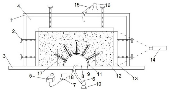
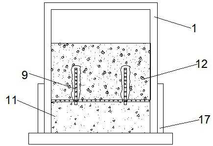
[0052] Such as figure 1 , figure 2 As shown, a centrifuge test device for a tunnel support system includes a base plate 3 and a model test cover 1 fixed on the base plate; symmetrical through holes are arranged on the side walls of the model test cover 1; the base plate 3 is fixed with Transparent rock-12; the inner water chamber 8 between the transparent rock-12 and the bottom plate 3; the inner water chamber 8 and the transparent rock-12 are supported by the lining 11; the two ends of the lining 11 are embedded in symmetrical through holes; the lining 11 The two ends are sealed by the sealing glass plate 17 that is close to the model test cover 1; the outer water chamber 4 is formed between the top of the transparent rock-12 and the top of the model test cover 1; the anchor rod 9 is installed on the lining 11; the anchor rod 9 is buried in transparent rock-12. Fluorescent agent is mixed in the outer water chamber 4 or the inner water chamber 8 .

[0053] The model test c...

Embodiment 2

[0075] Example 1 is a centrifugal test on the long-term combined load bearing effect of the basic support system of the tunnel under the condition that the internal water pressure is greater than the external water pressure. The simulated engineering background is the basic support structure in the Gaoling water tunnel. Long-term working performance; for conventional tunnels where the external water pressure is greater than the internal water pressure, the implementation of step (3) of the working method can be changed on the basis of Example 1. The inner water chamber 8 and the outer water chamber 4 are respectively filled with 66.7% calcium bromide solution, wherein the outer water chamber 4 is mixed with a fluorescent agent; the outer water pressure machine 16 is started to apply a water pressure value of 40.5MPa to the outer water chamber to keep the inner water chamber The water pressure value is 0 MPa constant; when fluorescent particles appear in the inner water chamber ...


PUM


Abstract

The invention discloses a centrifuge test device for a tunnel support system, a working method and a manufacturing method thereof, and belongs to the technical field of geotechnical engineering centrifuge model tests. It includes a bottom plate and a model test cover; the bottom plate and the model test cover are sealed to form an outer water chamber; a transparent rock is fixed on the bottom plate of the outer water chamber; an inner water chamber is formed between the transparent rock and the bottom plate; The water chamber and the transparent rock are supported by a lining; both ends of the lining are provided with sealing glass plates; the sealing glass plates are closely attached to the side walls of the model test cover; anchor rods are installed on the lining; Rods are buried in transparent rock. The invention has simple structure and strong implementation feasibility.

Description

technical field [0001] The invention relates to the technical field of geotechnical engineering centrifuge model tests, in particular to a centrifuge test device for a tunnel support system, a working method and a manufacturing method thereof. Background technique [0002] The basic principle of the rock-soil centrifugal model test is to place the geotechnical test device in a high-speed rotating centrifugal acceleration field, let the model bear the centrifugal acceleration movement of several times the acceleration of gravity, increase the bulk density of the model, and compensate for the loss caused by the scaling of the model. Self-weight loss of geotechnical structures. In the surrounding rock-lining-bolt combined bearing centrifugal test, by observing the deformation of the surrounding rock and lining during the test, it provides an effective means for the in-depth study of the working behavior of the basic support system of the tunnel. [0003] Existing devices can b...

Claims


Application Information

Patent Timeline
Patent Type & Authority Patents(China)
IPC IPC(8): G01N3/08G01N3/02
CPCG01N3/02G01N3/08G01N2203/0037G01N2203/0075
Inventor 倪小东徐硕陆江发姬良龙王媛
Owner HOHAI UNIV
Why Eureka
Try Eureka