A Simulation Method of Pipeline Fluid Flow Oriented to Virtual Chemical Experiment Teaching

A fluid flow, simulation method technology, applied in the field of computer simulation, to achieve the effect of visual simulation

Active Publication Date: 2018-04-24
南京运立仪器有限公司
View PDF3 Cites 0 Cited by
  • Summary
  • Abstract
  • Description
  • Claims
  • Application Information

AI Technical Summary

Problems solved by technology

[0004] The purpose of the present invention is to provide a simulation method for pipeline fluid flow oriented to virtual chemical engineering experiment teaching, to solve the simulation problem of the relationship between fluid flow state and pipe fitting state response in chemical engineering experiment, so as to achieve the goal of assisting experimental teaching and showing the experimental process and principle Purpose

Method used


Image

  • A Simulation Method of Pipeline Fluid Flow Oriented to Virtual Chemical Experiment Teaching
  • A Simulation Method of Pipeline Fluid Flow Oriented to Virtual Chemical Experiment Teaching
  • A Simulation Method of Pipeline Fluid Flow Oriented to Virtual Chemical Experiment Teaching

Examples


Embodiment 1

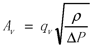
[0025] Take water passing through a DN15 single-piece ball valve in a DN15 (nominal diameter) stainless steel pipeline at 25°C as an example. The density of water at 25°C is 997kg / m 3 , the kinematic viscosity is 9.055*10 -7 m 2 / s, set the flow rate to 1*10 -3 m 3 / s, pipeline length L 1 , L 2 0.5m, valve flow coefficient A v 1.13*10 -6 , when developing the system, set the initial point a 1 pressure P 1a 0.1MPa, P 1b ,P 2a ,P 2b Both are 0MPa, add the script and particle system and release the system. Click the mouse to control the opening of the ball valve during operation. After opening, at this time b 1 Point pressure value P 1b (0MPa) less than a 1 pressure P 1a (0.1MPa), call the particle system, the fluid from a 1 point flow to b 1 Point, take the valve opening as 1 / 10, and the relational equation between flow rate and ball valve opening: Q / Q max =0.94x 3 -0.17x 2 +0.22x-0.01 calculates the flow velocity u=6.4*10 after passing through the valve -2...

Embodiment 2

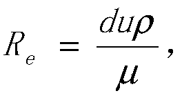
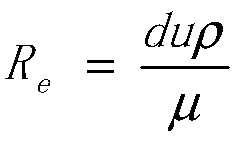
[0027] Other conditions are the same as in Example 1. When the valve opening becomes 1 / 2, P is obtained through the same calculation. 2a Point speed u=0.99m / s, Re=1.64*10 4 , the flow pattern at this time is turbulent flow, and the system calls the code when Re≥4000 to realize the visual simulation of the turbulent flow of the pipeline fluid at this time, and the effect is as follows image 3 shown.

Embodiment 3

[0029] When the fluid changes into other substances, the realization method of the fluid flowing between the pipeline and the valve is as above, and the simulation of the flow pattern only needs to change the physical parameters of the corresponding fluid and realize it with the same calculation method.


PUM


Abstract

The invention discloses a simulation method for pipeline fluid flow oriented to virtual chemical engineering experiment teaching. A pipeline model composed of pipelines and valves is established in 3ds max. An initial value, the valve connecting the two pipelines is used as the event trigger object, and the trigger event script code is added to the nodes at both ends of the pipeline and the event trigger object; when the system is running, when the state of the event trigger object is changed, the node at one end of the pipeline invokes the trigger event The script subscribes to the initial value of the node at the other end to change its own initial value, and changes the value of the node adjacent to the next pipeline through the association algorithm, and then calls the corresponding trigger event to realize the simulation according to the state of the event trigger object. The invention establishes a simple, effective and practical fluid flow state response relationship, realizes the visual simulation of pipeline fluid flow process and phenomenon, and helps users understand the fluid flow process.

Description

technical field [0001] The invention belongs to the field of computer simulation, and in particular relates to a simulation method for pipeline fluid flow oriented to virtual chemical engineering experiment teaching. Background technique [0002] The chemical unit operation experiment is based on the background of chemical production. After the large-scale production equipment of the factory is miniaturized, it is used for experimental teaching and the cultivation and training of advanced application-oriented and skilled talents. The chemical unit operation experiment device has a complex structure and is mostly made of stainless steel. During the experiment, it is often difficult for the experiment operator to understand the experiment process and principle due to the limitations of the device being invisible and non-detachable. [0003] With the increasing improvement of computer simulation technology, more and more attention has been paid to the simulation and visualizati...

Claims


Application Information

Patent Timeline
Patent Type & Authority Patents(China)
IPC IPC(8): G06F17/50G06F9/455
Inventor 林军杨广玉李明海何佳艺汪祖洁孙露静
Owner 南京运立仪器有限公司
Why Eureka
Try Eureka