Lens assembly

A lens assembly and lens technology, applied in optical components, electrical components, color TV components, etc., can solve the problems of high cost, heavy weight and high power consumption, and achieve the effects of high reliability, simple structure and convenient installation.

Active Publication Date: 2019-08-16
AAC OPTICS SOLUTIONS PTE LTD
View PDF5 Cites 8 Cited by
  • Summary
  • Abstract
  • Description
  • Claims
  • Application Information

AI Technical Summary

Problems solved by technology

The lens module in this embodiment moves under the action of electromagnetic force, which is easily disturbed by the magnetic field, and additional Hall elements are needed to detect the shaking of the lens barrel, which has poor reliability in special environments; in addition, the anti-shake The structure includes OIS coils and magnets. The overall structure is complex, costly, and heavy. In addition, a large current needs to be passed through the OIS coil to form a large electromagnetic force to drive the magnet to prevent the OIS bracket and the optical axis from shifting. Power consumption high
In summary, the existing optical anti-shake structure of the lens module cannot meet the market requirements of light weight, low power consumption, low cost and high reliability

Method used


Image

  • Lens assembly
  • Lens assembly
  • Lens assembly

Examples


Embodiment Construction

[0033] The present invention will be further described below in conjunction with the accompanying drawings and embodiments.

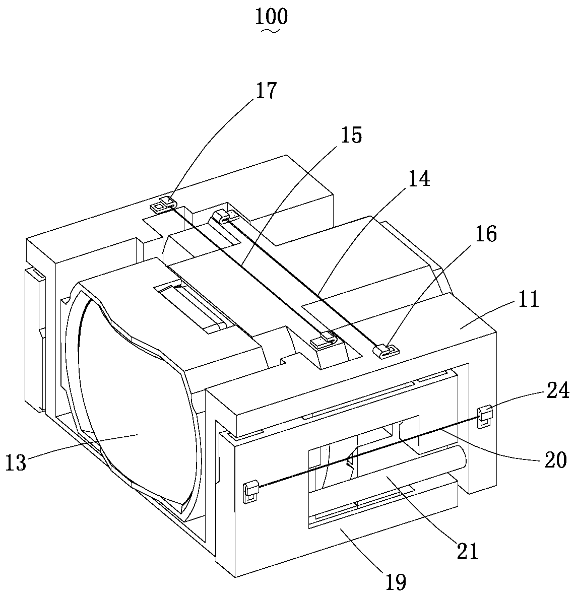
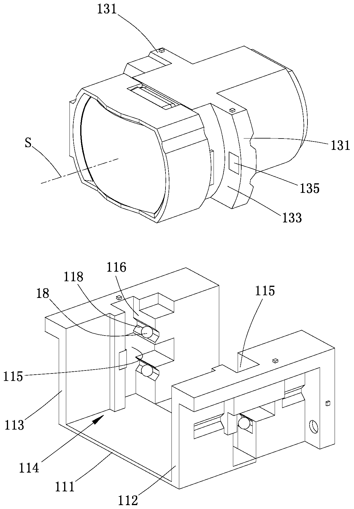
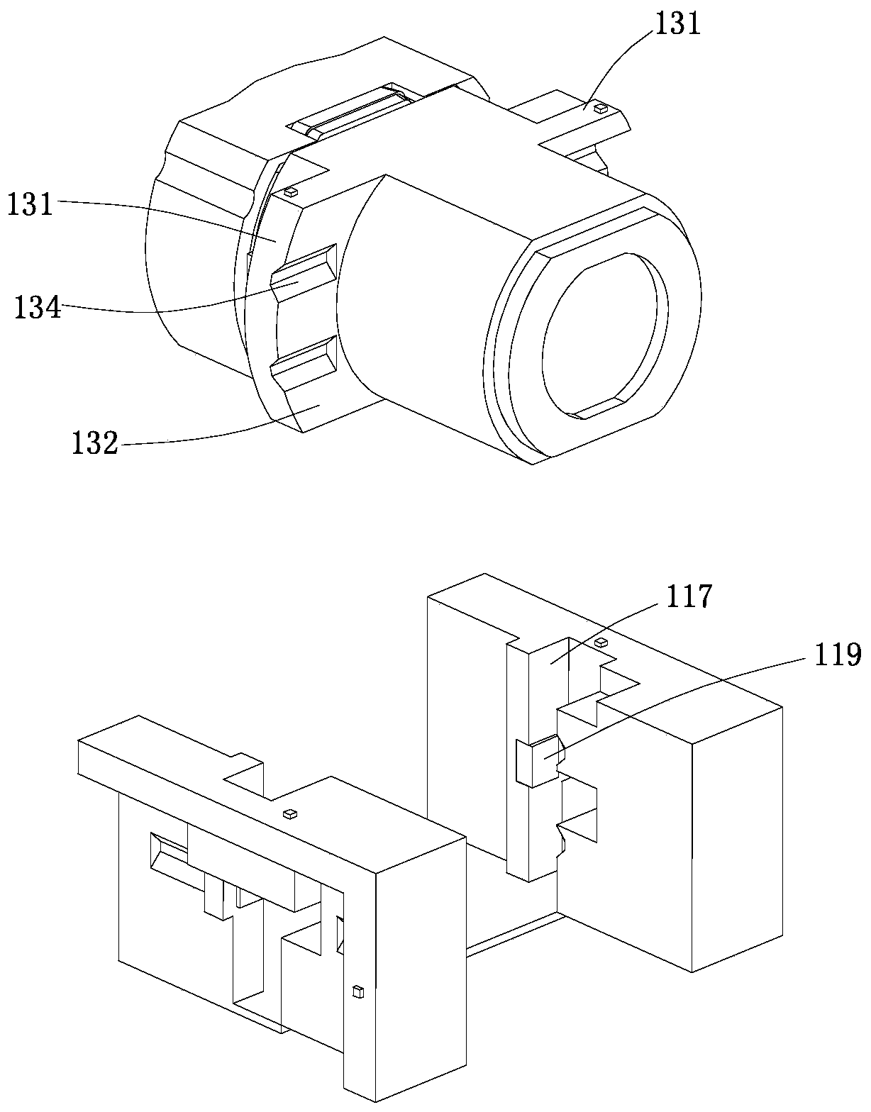
[0034] see Figure 1-3 , The embodiment of the present invention provides a lens assembly 100 including a first base 11 , a lens 13 , a first memory alloy wire 14 and a second memory alloy wire 15 , and the lens 13 is slidably installed in the first base 11 . The first base 11 includes a first bottom plate 111, a first side plate 112 arranged on one side of the first bottom plate 111 and a second side plate 113 arranged on the other side of the first bottom plate 111, the first bottom plate 111, the first side The plate 112 and the second side plate 113 surround and form a first installation groove 114 , the lens 13 is installed in the first installation groove 114 , and the first side plate 112 and the second side plate 113 are respectively located on opposite sides of the lens 14 . The first memory alloy wire 14 and the second memory alloy wire 15 ar...


PUM


Abstract

The invention provides a lens assembly. The lens assembly comprises a first substrate, a lens, a first memory alloy wire and a second memory alloy wire, wherein the lens is arranged in the first substrate in a sliding way, the first substrate comprises a first side plate and a second side plate, the first side plate is arranged at one side of the lens, the second side plate is arranged at the other side of the lens, one end of the first memory alloy wire is connected with the first side plate, the other end of the first memory alloy wire is connected with the lens, one end of the second memoryalloy wire is connected with the second side plate, the other end of the second memory alloy wire is connected with the lens, and the first memory alloy wire and the second memory alloy wire both arearranged perpendicular to an optical axis of the lens. In the lens assembly provided by the invention, the lens is driven to move relative to the first side plate and the second side plate in a reciprocating way to achieve optical vibration prevention by enabling the first memory alloy wire and the second memory alloy wire to be energized and deformed, no problem of magnetic interference exists,and the stability is relatively high; and moreover, by a driving setting mode, the lens assembly is simple in structure and is convenient to install, no extra hall component is needed to be arranged,and the lens assembly is high in reliability used under a special environment.

Description

[0001] 【Technical field】 [0002] The invention relates to the technical field of lens optical imaging, in particular to a lens assembly. [0003] 【Background technique】 [0004] In recent years, high-performance lens modules have been mounted on portable terminals such as smartphones and tablet computers. The high-performance lens module generally has an auto focusing function (auto focusing) and an optical image stabilization function (OIS: optical image stabilization). [0005] The optical anti-shake function of the existing camera lens module is to sense the offset between the OIS bracket and the optical axis through the Hall sensor, and input current to the OIS coil, and the OIS coil cooperates with a magnet to prevent the OIS bracket and the optical axis from shifting. Return it to its original position. The lens module in this embodiment moves under the action of electromagnetic force, which is easily disturbed by the magnetic field, and additional Hall elements are ne...

Claims


Application Information

Patent Timeline
Patent Type & Authority Applications(China)
IPC IPC(8): G02B7/09G03B5/00G03B13/36H04N5/225H04N5/232G03B30/00
CPCG02B7/09G03B13/36G03B5/00H04N23/55H04N23/687G02B27/646G02B7/08G02B13/001
Inventor 李林珍卢继亮李刚张晋
Owner AAC OPTICS SOLUTIONS PTE LTD
Why Eureka
Try Eureka