Microscope observation head which is convenient for installation and positioning

A technology for installation and positioning of microscopes, which is applied in the field of microscopes, can solve problems such as unsuitability, troublesome disassembly, ugly clear images, etc., and achieve the effect of convenient disassembly and convenient positioning

Pending Publication Date: 2019-08-16
NINGBO TEACHING INSTR
View PDF0 Cites 0 Cited by
  • Summary
  • Abstract
  • Description
  • Claims
  • Application Information

AI Technical Summary

Problems solved by technology

[0002] There are usually multiple prisms inside the observation head of the microscope, but all current prisms are fixed on the frame by screws, which leads to the need to disassemble the screws in the later disassembly, which makes the later disassembly relatively troublesome, and the screws are generally screwed through the outside of the frame. If it goes in, the internal positioning will be inaccurate, and deviations will easily occur during later observation, and the interpupillary distance used on the current observation head is 55~75mm. Because the interpupillary distance between the eyes of some people is relatively small, it is not suitable for the present Some microscope observation heads watch, in summary, there are currently two technical problems: 1. The positioning of the prism is not accurate, which makes it difficult to see clear images on the microscope observation head; 2. It cannot be used by a wider range of people.

Method used


Image

  • Microscope observation head which is convenient for installation and positioning
  • Microscope observation head which is convenient for installation and positioning
  • Microscope observation head which is convenient for installation and positioning

Examples


Embodiment 1

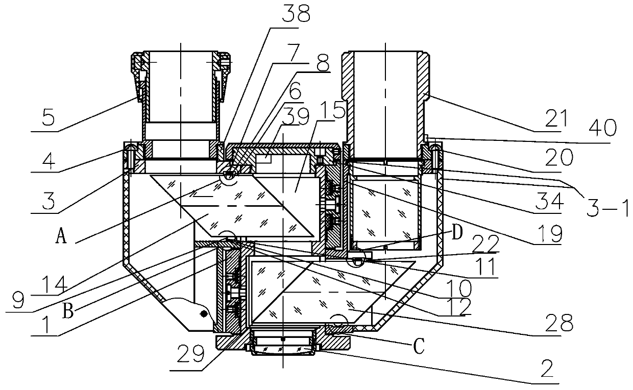
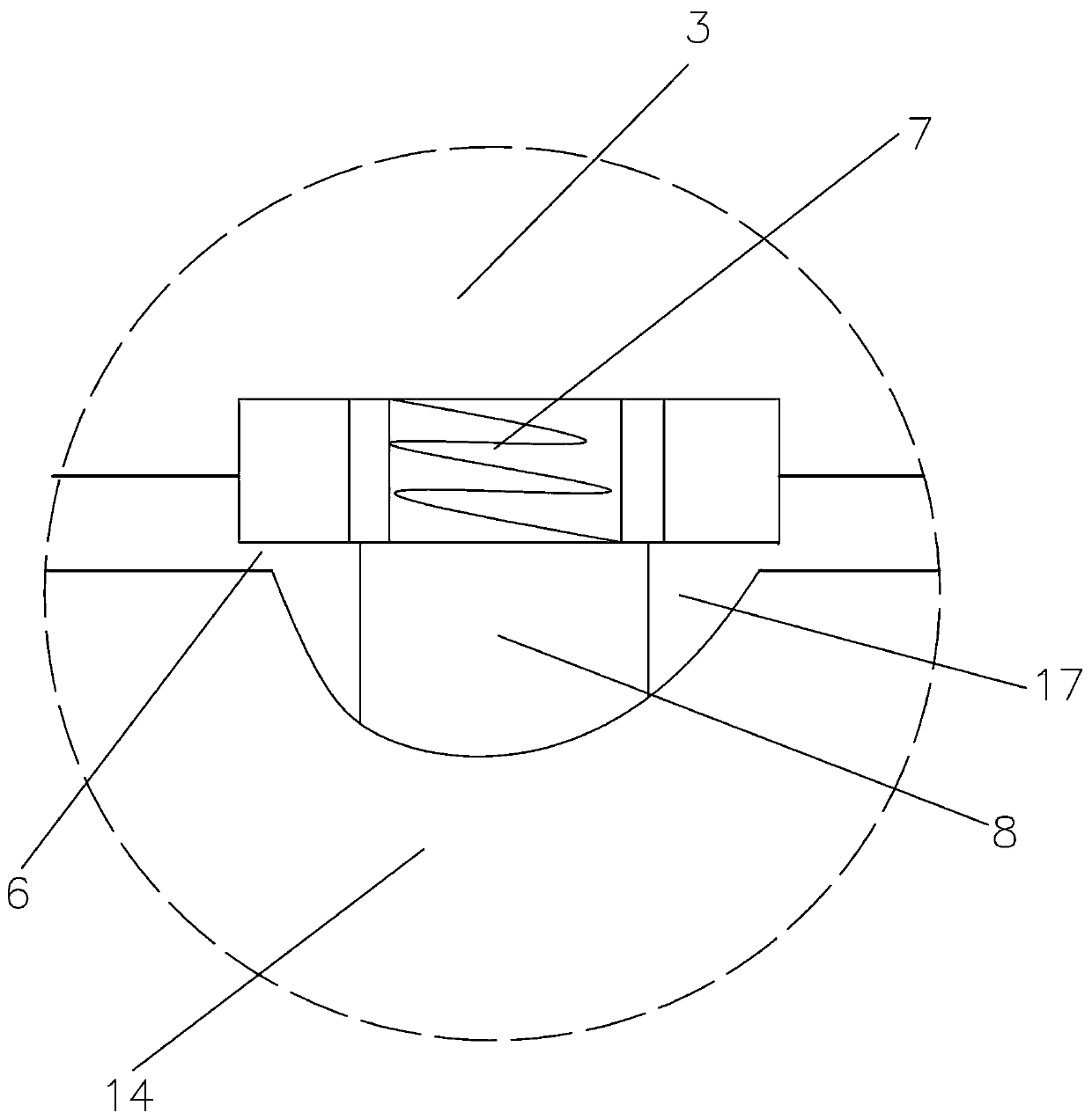
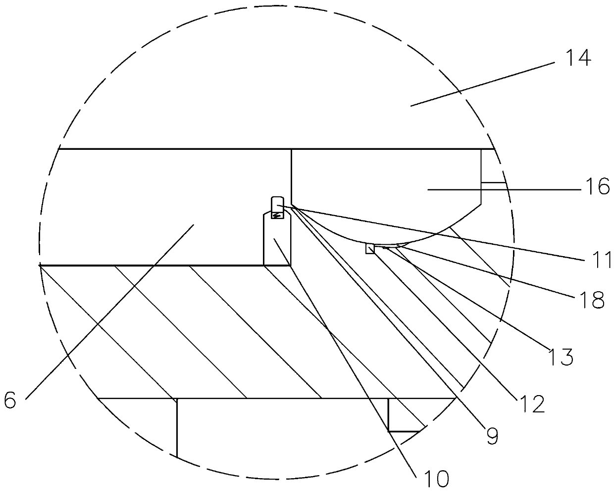
[0022] Such as Figure 1-Figure 8 As shown, a microscope observation head that is convenient for installation and positioning provided in this embodiment includes a rotating shaft 1, and a lens 2 is arranged under the rotating shaft 1, and lens 2 is arranged symmetrically on the left and right sides of the rotating shaft 1, which can be adjusted by rotating around the rotating shaft 1. The left viewing assembly and the right viewing assembly of the size of the interpupillary distance, the left viewing assembly includes a left prism support 3 that can rotate around the axis line of the rotating shaft 1, and a screw 4 that can turn inward is fixed above the left prism support 3. The left eyepiece tube 5 for observation is provided with a first notch 6 on one side of the left prism support 3, a first spring 7 is fixed on the upper wall of the first notch 6, and a first limit post is fixed below the first spring 7 8. A first groove 9 is provided below the first notch 6, a first li...


PUM


Abstract

The invention discloses a microscope observation head which is convenient for installation and positioning. The microscope observation head which is convenient for installation and positioning comprises a rotating shaft and a pupil distance marking disk; a lens is provided below the shaft internally; a left observation component and a right observation component capable of rotating around the rotating shaft to adjust the size of the pupil distance are symmetrically disposed on the left and right sides of the rotating shaft; the left observation component and the right observation component areidentical in structure and each includes a prism holder that can rotate around the axis of the rotating shaft; an eyepiece sleeve is fixed above the prism holder; a gap is disposed on one side of theprism holder; a spring is fixed on the upper wall of the gap; a limiting column is fixed under the spring; a groove is provided below the gap; a contact switch and an electromagnet are arranged in the groove; a prism aligned with the corresponding eyepiece sleeve is fitted between the limiting column and the groove; an iron piece matched with the corresponding electromagnet is arranged on the prism; and when the two prism holders are rotated, the distance between the centers of the two eyepiece sleeves is guaranteed to be between 48 and 75 mm. The microscope observation head which is convenient for installation and positioning facilitates later disassembly and positioning.

Description

technical field [0001] The invention relates to the field of microscopes, and is specially designed to facilitate installation and positioning of a microscope observation head. Background technique [0002] There are usually multiple prisms inside the observation head of the microscope, but all current prisms are fixed on the frame by screws, which leads to the need to disassemble the screws in the later disassembly, which makes the later disassembly relatively troublesome, and the screws are generally screwed through the outside of the frame. If it goes in, the internal positioning will be inaccurate, and deviations will easily occur during later observation, and the interpupillary distance used on the current observation head is 55~75mm. Because the interpupillary distance between the eyes of some people is relatively small, it is not suitable for the present Some microscope observation heads are used for viewing. To sum up, there are currently two technical problems: 1. T...

Claims


Application Information

Patent Timeline
Patent Type & Authority Applications(China)
IPC IPC(8): G02B21/20G02B21/24
CPCG02B21/20G02B21/24
Inventor 张浩杰
Owner NINGBO TEACHING INSTR
Why Eureka
Try Eureka