
A controller for limiting the temperature inside the switch cabinet

A controller, internal temperature technology, applied in temperature control, substation/switchgear cooling/ventilation, control/regulation system, etc., can solve problems such as equipment failure, circuit box burning, loss of combustibles, etc., to save copper pipes material, increase the heat absorption area, and avoid the effect of loss

Active Publication Date: 2020-11-24
HUAINAN WANTAI RONGBO LIGHTING TECH
View PDF11 Cites 0 Cited by
  • Summary
  • Abstract
  • Description
  • Claims
  • Application Information

AI Technical Summary

Problems solved by technology

[0002] The circuit box has a safe operating temperature range during operation. Too high temperature can cause the circuit box to burn, and even spread to the surrounding combustible objects to cause unpredictable losses. Too low temperature will cause the internal components of the circuit box to lose their operation. Ability to cause shutdown and, in severe cases, serious failure of equipment
[0003] At present, the temperature of the circuit box is set through holes on the circuit box, and the temperature inside the circuit box is taken away by the flow of natural wind, or a temperature sensing element is installed in the circuit box to transmit the temperature to the control center in real time. If the temperature exceeds the range time to respond, however such a response has often already caused serious damage, e.g. fire
In order to reduce the risk of fire caused by too high temperature of the circuit box, or the risk of failure of the circuit box caused by too low temperature, there is currently no good way, and this invention also focuses on solving this problem

Method used


Image

  • A controller for limiting the temperature inside the switch cabinet
  • A controller for limiting the temperature inside the switch cabinet
  • A controller for limiting the temperature inside the switch cabinet

Examples


Embodiment Construction

[0032] The technical solutions in the embodiments of the present invention will be clearly and completely described below in conjunction with the embodiments of the present invention. Apparently, the described embodiments are only some of the embodiments of the present invention, not all of them. Based on the embodiments of the present invention, all other embodiments obtained by persons of ordinary skill in the art without creative efforts fall within the protection scope of the present invention.

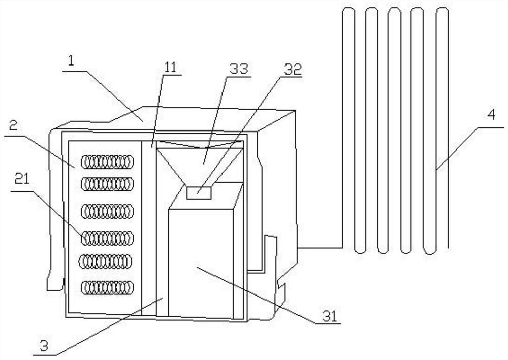
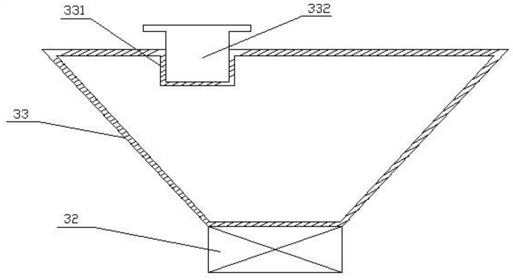
[0033] see Figure 1-Figure 5 As shown, the present invention is a controller for limiting the temperature in a switchgear cabinet, including a controller outer box 1, and also includes a heat control box 2, a cold control box 3 and a heat absorption pipe 4, and the heat control box 2 and the cold control box The control box 3 is arranged inside the controller outer box 1, and the heat-absorbing pipe 4 is installed outside the controller outer box 1. The heat control box 2 and the...


PUM


Abstract

The invention discloses a controller for limiting inside temperature of a switch cabinet, and the controller comprises a controller outer box, and further comprises a heat control box, a cold controlbox and a heat absorption tube, wherein the heat control box and the cold control box are arranged inside the controller outer box, the heat absorbing tube is installed outside the controller outer box, the heat control box and the cold control box are separated by a heat insulating layer, a plurality of resistance coils are installed inside the heat control box, a water tank is installed inside the cold control box, a sealed box is installed above the water tank, and one end of the water tank is installed with one end of the heat absorbing tube. The controller of the invention, from the pointof view of the temperature controller itself regulating the internal temperature of the circuit box, provides a temperature to guarantee the normal operation of the circuit box when exceeding the normal working temperature in an extremely cold environment, and delays the burning temperature inside the circuit box through the heat absorption of chemical reaction in an extremely hot environment, sothat the circuit box can be safely used to delay the occurrence of danger.

Description

technical field [0001] The invention relates to the technical field of temperature control, in particular to a controller for limiting the temperature inside a switch cabinet. Background technique [0002] The circuit box has a safe operating temperature range during operation. Excessively high temperature can cause the circuit box to burn, and even affect the surrounding combustible objects, resulting in unpredictable losses. Too low temperature will cause the internal components of the circuit box to lose operation. Ability to cause shutdown and, in severe cases, serious failure of equipment. [0003] At present, the temperature of the circuit box is set through holes on the circuit box, and the temperature inside the circuit box is taken away by the flow of natural wind, or a temperature sensing element is installed in the circuit box to transmit the temperature to the control center in real time. If the temperature exceeds the range time to respond, however such a respo...

Claims


Application Information

Patent Timeline
Patent Type & Authority Patents(China)
IPC IPC(8): G05D23/20H02B1/56
CPCG05D23/20H02B1/565
Inventor 李建书陈浩桂要张立春王龙王怀丰
Owner HUAINAN WANTAI RONGBO LIGHTING TECH
Learn More