Bone rehabilitation external fixing frame with stepless adjusting jig

A technology of stepless adjustment and external fixation frame, which is applied in orthopedic correction and rehabilitation fields. It can solve problems such as difficult adjustment of the size of the fixation ring, difficult operation, and steel needle deviation, so as to reduce the operation intensity, reduce model requirements, and reduce The effect of movement restriction

Pending Publication Date: 2019-08-20
ZHEJIANG UNIV OF TECH
View PDF0 Cites 1 Cited by
  • Summary
  • Abstract
  • Description
  • Claims
  • Application Information

AI Technical Summary

Problems solved by technology

[0010] The purpose of the present invention is to solve the problem that in the existing field of orthopedic rehabilitation, a series of fixed rings must be selected according to the patient’s condition. The size of the fixed rings is difficult to adjust and the traditional clamps cannot perfectly match the position of the needle. When the steel needle is nailed into the patient's bone, it is easy to miss the steel needle and need to be nailed again, causing secondary or even multiple injuries, which makes the operation difficult, high threshold, and brings great pain to the patient. , proposed a bone rehabilitation external fixator with stepless adjustable clamps. The size of the fixator can be adjusted by adjusting the position of the nut and removing the connector, which can realize fine-tuning fixation and needle-guiding, which can not only improve clinical fracture The accuracy and safety of the reset, and reduce the operating intensity of the clinician, greatly improving the success rate of the operation, and the length of the rod can be adjusted by driving the electric push rod, or the length can be adjusted by the screw. After the motor adjustment is completed Can also be easily disassembled

Method used


Image

  • Bone rehabilitation external fixing frame with stepless adjusting jig
  • Bone rehabilitation external fixing frame with stepless adjusting jig
  • Bone rehabilitation external fixing frame with stepless adjusting jig

Examples


Embodiment Construction

[0047] The present invention will be further described below in conjunction with accompanying drawing:

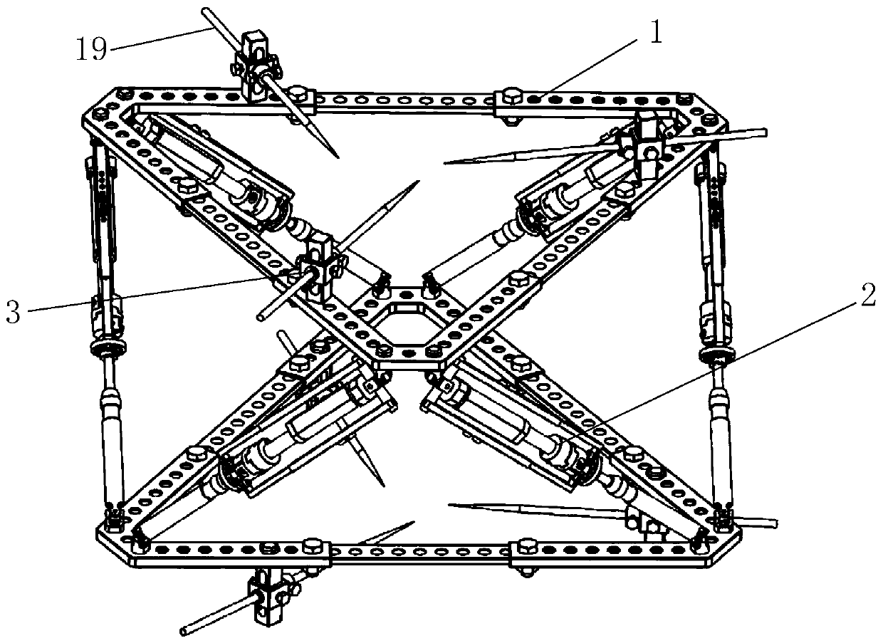
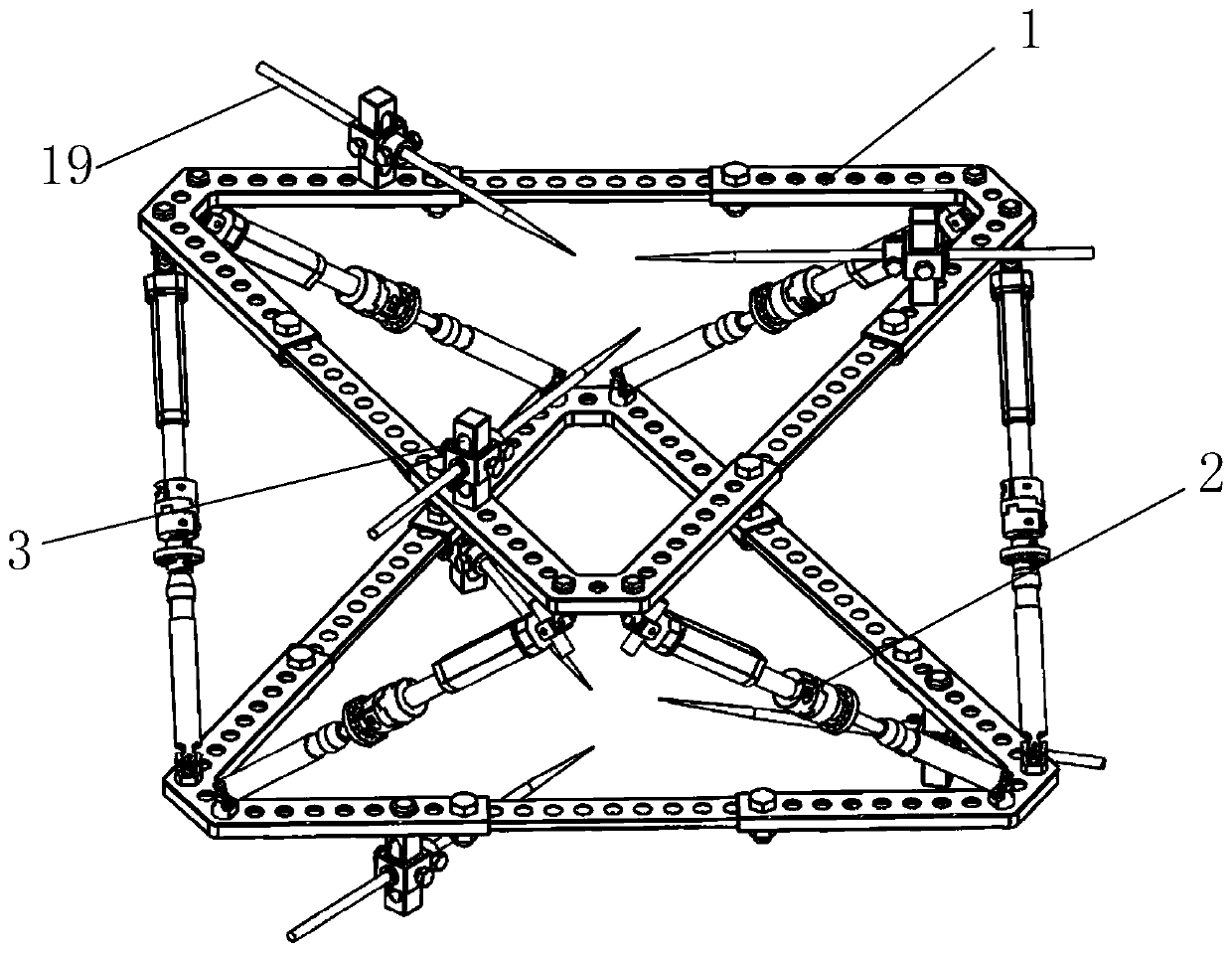
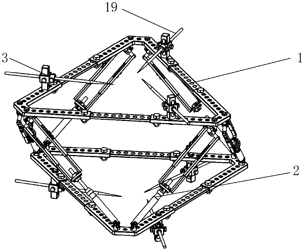
[0048] Such as Figure 1~3 As shown, a bone rehabilitation external fixator with stepless adjustable clamps includes a telescopic fixation ring module 1, a detachable linkage mechanism 2 and a stepless adjustment needle threading fixture 3, and the telescopic fixation ring module 1 is set There is a pair of upper and lower symmetrical sets. The telescopic fixed ring module 1 is connected by six detachable linkage mechanisms 2. The stepless adjustment needle threading fixture 3 for clamping the steel needle 19 is fixed on the telescopic fixed ring module 1. After a plurality of steplessly adjustable needle threading fixtures 3 are fixed on the telescopic fixing ring module 1, steel needles 19 on these steplessly adjustable needle threading fixtures 3 are used to penetrate into the patient's bone to realize the stepless adjustable bone rehabilitation exterior of the fixtures....


PUM


Abstract

The invention discloses a bone rehabilitation external fixing frame with a stepless adjusting jig. The external fixing frame comprises telescopic fixing ring modules, detachable connecting rod mechanisms and stepless adjusting needle threading jigs, wherein the telescopic fixing ring modules are connected through the six detachable connecting rod mechanisms, and the stepless adjusting needle threading jigs are fixed on the telescopic fixing ring modules; and each telescopic fixing ring module comprises corner kits, linear inserts, fixing bolts and tightening nuts, and each stepless adjusting needle threading jig comprises an adjusting upright post, a steel needle sleeve, a fixing nut, an upper-lower locking bolt, a front-rear locking bolt and an adjusting slide block. According to the invention, the size of the fixing ring can be adjusted by adjusting the position of the nuts and removing connecting pieces, so that the applicability and the compatibility of the device are improved; andthe invention provides a design of a detachable electric push rod, and the design comprises the following steps: firstly, connecting a replacement connecting device to two ends of a linear push rod through bolts, keeping the positions of the two ends unchanged, then dismantling the electric push rod, and replacing the electric push rod with an alternative screw rod device.

Description

technical field [0001] The present invention relates to the field of orthopedic correction and rehabilitation, and more specifically, relates to an external fixator for bone rehabilitation with stepless adjustable clamps. Background technique [0002] During bone surgery, fixation devices are indispensable. Traditional fixation methods generally use internal fixation with steel plates, and now there are also external fixation treatment methods with less trauma. Commonly used external fixation devices are mainly Ilizarov external fixator and Taylor frame. The Ilizarov technique uses multiplanar thin Kirschner wires to penetrate the limb and bone tissue and connect to a ring fixator. Dr. Taylor improved the Ilizarov external fixation system by connecting six telescopic extension rods obliquely to the proximal and distal rings, and they can rotate freely at the connection point. As long as the length of one of the extension rods is adjusted, one ring will Change position rela...

Claims


Application Information

Patent Timeline
Patent Type & Authority Applications(China)
IPC IPC(8): A61B17/62
CPCA61B17/62
Inventor 杨庆华孙威陈一钦叶真孜方航李鹏翔潘隽荀一
Owner ZHEJIANG UNIV OF TECH
Why Eureka
Try Eureka