Uncoiler uncoiling operation method

An operation method and uncoiler technology, which is applied in the field of lap joints between steel coils and steel coils, can solve the problems that the steel coils cannot enter the lap joint smoothly, and achieve the goal of improving the effective operation rate and uncoiling efficiency Effect

Active Publication Date: 2020-08-14
LIUZHOU IRON & STEEL
View PDF11 Cites 0 Cited by
  • Summary
  • Abstract
  • Description
  • Claims
  • Application Information

AI Technical Summary

Problems solved by technology

[0003] The technical problem to be solved by the present invention is to provide an uncoiling operation method of an uncoiler to solve the problem that the existing steel coil cannot smoothly enter the steel plate conveying channel of the uncoiler and overlap the tail of the previous coil

Method used


Image

  • Uncoiler uncoiling operation method
  • Uncoiler uncoiling operation method
  • Uncoiler uncoiling operation method

Examples


Embodiment 1

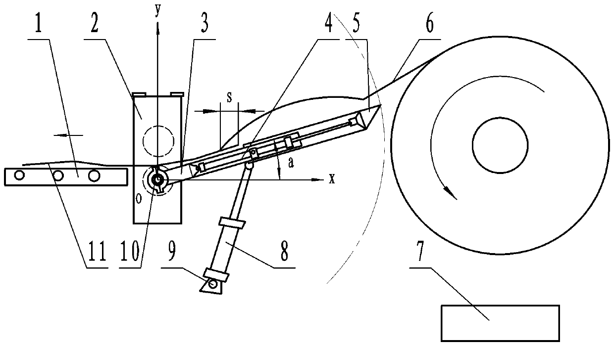
[0022] An uncoiler uncoiling operation method, such as image 3 and Figure 4 The shown uncoiler has a frame body 2 provided with a steel plate conveying channel, the frame body 2 is adjacent to the conveyor belt 1, a guide plate device is used, and the guide plate device includes a hinge shaft 10, the hinge shaft 10 of this embodiment is installed On the frame body 2 below the steel plate conveying channel; on the hinge shaft 10, a fixed cover plate 3 protruding from the frame body 2 is hinged, and the rear end of the fixed cover plate 3 protrudes from the rear of the frame body 2; the fixed cover plate 3 Connected with the lifting power cylinder, the lifting power cylinder of the embodiment is the lifting hydraulic cylinder 8, the fixed end of the lifting hydraulic cylinder 8 is installed on the support 9, and the support 9 is fixed on the ground; the movable end of the lifting hydraulic cylinder 8 is connected On the bottom surface of the fixed sleeve plate 3; the fixed sl...

Embodiment 2

[0029] An uncoiler uncoiling operation method, such as image 3 and Figure 4 The shown uncoiler has a frame body 2 provided with a steel plate conveying channel, the frame body 2 is adjacent to the conveyor belt 1, a guide plate device is used, and the guide plate device includes a hinge shaft 10, the hinge shaft 10 of this embodiment is installed On the frame body 2 below the steel plate conveying channel; on the hinge shaft 10, a fixed cover plate 3 protruding from the frame body 2 is hinged, and the rear end of the fixed cover plate 3 protrudes from the rear of the frame body 2; the fixed cover plate 3 Connected with the lifting power cylinder, the lifting power cylinder of the embodiment is the lifting hydraulic cylinder 8, the fixed end of the lifting hydraulic cylinder 8 is installed on the support 9, and the support 9 is fixed on the ground; the movable end of the lifting hydraulic cylinder 8 is connected On the bottom surface of the fixed sleeve plate 3; the fixed sl...


PUM

PropertyMeasurementUnit
lengthaaaaaaaaaa

Abstract

The invention discloses an uncoiler uncoiling operation method. The method comprises the following steps of A, starting a lifting power cylinder when a previous coil of steel coil strip tail is advanced to a sliding sleeve plate, enabling a fixed sleeve plate stopping after rotating a first quadrant oblique angle, and starting a telescopic power cylinder to enable the sliding sleeve plate to extend out of the fixed sleeve plate; B, enabling a conveyor belt to stop advancing so as to enable the steel coil strip tail can stay on the fixed sleeve plate when the previous coil of steel coil strip tail are all fed into the fixed sleeve plate; C, overlapping a next coil of steel coil strip head to the previous coil of steel coil strip tail, starting the conveying belt to enable the next coil of steel coil to enter the conveying belt under traction of the previous coil of steel coil; and D, starting the lifting power cylinder when the next coil of steel coil strip tail enters the conveying belt, enabling the fixed sleeve plate stopping after rotating a fourth quadrant oblique angle clockwise, and meanwhile, starting the telescopic power cylinder to enable the sliding sleeve plate to retract into the fixed sleeve plate. Compared with the prior art, the method can be used for solving the problem that a strip head of an existing steel coil cannot smoothly enter a steel plate conveying channel of an uncoiler to be overlapped with a strip tail of a steel coil of a previous coil.

Description

technical field [0001] The invention relates to the technical field of overlapping the tape head and tail of steel coils, in particular to a method for overlapping the tape heads and tails of two steel coils by using an uncoiler. Background technique [0002] The uncoiler is one of the important equipment in the heavy coil tension leveler unit. The uncoiler has a frame body with a steel plate conveying channel. The frame body is respectively equipped with a pair of conveying rollers arranged up and down on the steel plate conveying channel; The strip head of the steel coil straightened by the straightening machine is sent to the welding machine through the steel plate conveying channel of the uncoiler to overlap with the strip tail of the previous coil, so that the welder can weld the steel coil of the next coil The belt head is welded to the tail of the steel coil of the previous coil; the currently used five-roll leveling machine includes three lower rollers arranged at in...

Claims


Application Information

Patent Timeline
Patent Type & Authority Patents(China)
IPC IPC(8): B21C47/18B21C47/26B21C47/34
CPCB21C47/18B21C47/26B21C47/3433
Inventor 肖胜黄运刚黄福德陈柳军欧坪鑫
Owner LIUZHOU IRON & STEEL
Why Eureka
Try Eureka