Rotor and stator unsheathing device

A technology of rotor stator and sleeve removal, applied in electromechanical devices, manufacturing motor generators, electrical components, etc., can solve the problems of difficult separation and sleeve removal, low sleeve removal efficiency, etc.

Inactive Publication Date: 2020-10-20
苏州勋空自动化设备有限公司
View PDF0 Cites 0 Cited by
  • Summary
  • Abstract
  • Description
  • Claims
  • Application Information

AI Technical Summary

Problems solved by technology

[0002] In order to reduce the transportation cost, the rotor and the stator are generally assembled together and sent together. When the manufacturer needs to use the rotor and stator for assembly, it is generally necessary to separate the rotor and the stator, and th

Method used


Image

  • Rotor and stator unsheathing device
  • Rotor and stator unsheathing device
  • Rotor and stator unsheathing device

Examples


Embodiment Construction

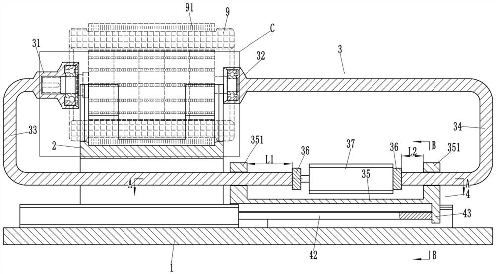
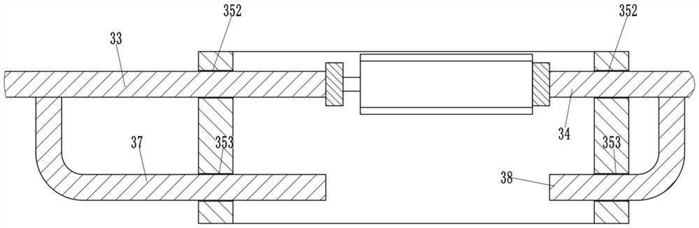
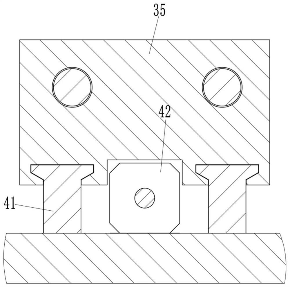
[0020] Examples, see e.g. Figure 1 to Figure 5 As shown, a rotor stator unsleeving device includes a base plate 1, on which a stator positioning seat 2 is fixed, and the left end and the right end of the stator positioning seat 2 are respectively provided with a rotor clamping mechanism 3, and the rotor clamping mechanism 3 includes The left indenter 31 and the right indenter 32 that are arranged on the same axis, the left indenter 31 is fixed on one end of the first U-shaped bar 33, the right indenter 32 is fixed on one end of the second U-shaped bar 34, and the first U-shaped bar The other end of 33 and the other end of the second U-shaped bar 34 pass through the extended end of the corresponding guide hole 352 on the two side plates 351 of the U-shaped guide seat 35 to be fixed with a stopper 36, and the two stoppers 36 are respectively It is fixed on the piston rod and the cylinder body of the first oil cylinder 37; the guide seat 35 is provided with a translation mechani...


PUM


Abstract

The invention discloses a rotor and stator unsheathing device, which comprises a bottom plate. A stator positioning seat is fixed on the bottom plate; the left end and the right end of the stator positioning seat are respectively provided with a rotor clamping mechanism. The rotor clamping mechanism comprises a left pressing head and a right pressing head which are coaxially arranged; the left pressing head is fixed to one end of the first U-shaped rod, the right pressing head is fixed to one end of the second U-shaped rod, the extending ends of the other end of the first U-shaped rod and theother end of the second U-shaped rod penetrating through the corresponding guide holes in the two side plates of the U-shaped guide base are fixedly provided with check blocks, and the two check blocks are fixed to a piston rod and a cylinder body of the first oil cylinder. The guide seat is provided with a translation mechanism for driving the guide seat to move left and right. The rotor is fixedthrough the rotor clamping mechanism, the rotor is separated from the stator by horizontally moving the rotor clamping mechanism, workers can be assisted in easily separating the rotor from the stator, and the unsheathing efficiency is greatly improved.

Description

technical field [0001] The invention relates to the technical field of motor production, in particular to a rotor stator unwinding device. Background technique [0002] In order to reduce the transportation cost, the rotor and the stator are generally assembled together and sent together. When the manufacturer needs to use the rotor and stator for assembly, it is generally necessary to separate the rotor and the stator, and then install them on the corresponding body one by one; but because the rotor There is magnetism on the top, the rotor and the stator are tightly adsorbed together, it is difficult for the staff to easily separate the two, and the unwinding efficiency is relatively low. Contents of the invention [0003] The purpose of the present invention is to overcome the deficiencies of the prior art, and provide a rotor stator uncoupling device, which fixes the rotor through the rotor clamping mechanism, and separates the rotor from the stator through the translat...

Claims


Application Information

Patent Timeline
IPC IPC(8): H02K15/00B23P19/027
CPCB23P19/027H02K15/00
Inventor 徐勋美
Owner 苏州勋空自动化设备有限公司
Why Eureka
Try Eureka