
Water flow heating body

A heating body, water flow technology, applied in lighting and heating equipment, household heating, heating fuel and other directions, can solve the problems of high energy consumption, slow heating speed, increased operating costs, etc., to save operating costs and reduce energy consumption , to ensure the effect of heat conversion efficiency

Pending Publication Date: 2019-08-20
天津华创能源科技有限公司
View PDF0 Cites 1 Cited by
  • Summary
  • Abstract
  • Description
  • Claims
  • Application Information

AI Technical Summary

Problems solved by technology

Today's electric heating method needs to energize the heating tube to make the heating tube generate heat, and then exchange heat with the cold fluid. This method generally has disadvantages such as high energy consumption, low electrothermal conversion efficiency, and slow heating speed, which leads to increased operating costs, and When there is no fluid flow in the equipment, the heating tube will dry-burn due to continuous power supply, and the safety of the equipment is not good.

Method used


Image

  • Water flow heating body
  • Water flow heating body
  • Water flow heating body

Examples


Embodiment Construction

[0015] In order to enable those skilled in the art to better understand the technical solutions of the present invention, the present invention will be further described in detail below in conjunction with the accompanying drawings and preferred embodiments.

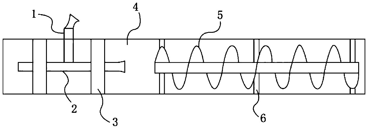
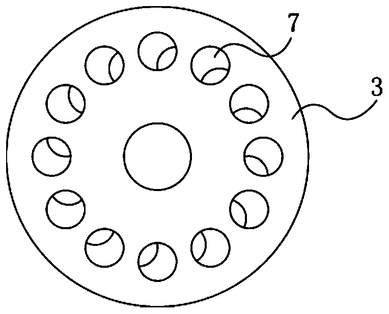
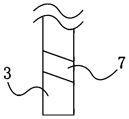
[0016] As shown in the figure, the present invention includes a heating pipeline 4, a bubble generating part and a vortex part arranged inside the heating pipeline 4, and the bubble generating part and the vortex part are arranged in sequence along the water flow direction, and the bubble generating part includes a baffle 3 , an inner pipe 2 and an air intake pipe 1, the inner pipe 2 is provided with a plurality of baffles 3 along the axial direction, the outer wall of the inner pipe 2 is fixedly connected to the center of the baffles 3, and the edges of the baffles 3 are fixed to the inner wall of the heating pipe 4 Then, the surface of the baffle plate 3 is evenly opened with a plurality of inclined holes 7, and the set...


PUM


Abstract

The invention relates to a water flow heating body which comprises a heating pipeline, a bubble generation portion and a vortex portion. The bubble generation portion comprises baffles, an inner pipeand an air inlet pipe. The multiple baffles are arranged on the inner pipe in the axial direction. The edges of the baffles are fixedly connected with the inner wall of the heating pipeline. Multipleinclined holes are evenly formed in the surface of each baffle. The inner pipe communicates with the air inlet pipe. The end of the air inlet pipe penetrates through the heating pipeline to extend outwards. According to the heating body, through strong pushing force of a circulating water pump at the front end of the heating pipeline, water entering the heating pipeline obtains a certain accelerated speed; due to the fact that a negative pressure cavity is formed in the inner pipe, water and air are mixed through the air inlet pipe to form multiple micron-order bubbles, then the bubbles enterthe vortex portion to forma vortex, severe extrusion, friction and exploding happen between the bubbles and the pipe wall and between the bubbles, and therefore the function of heating is achieved; and in the process, no external power source is needed for heating the heating pipeline, to-be-heated fluid is subjected to high-speed extrusion and colliding through kinetic energy, the heat conversionefficiency is ensured, meanwhile, energy consumption is effectively reduced, and the operation cost is saved.

Description

technical field [0001] The invention relates to a heater, in particular to a water flow heating body. Background technique [0002] The heating in the prior art is mainly based on the structural form of boiler, gas furnace and electric heating, which is mainly a device for transferring heat generated by material energy and electric energy to cold fluid. At present, with the improvement of heating technology, the requirements for heating units are getting higher and higher. Heating units provide heating heat source through electric heating is a clean and efficient heating method, which has been widely used in daily life and industrial fields. It brings convenience to users. Today's electric heating method needs to energize the heating tube to make the heating tube generate heat, and then exchange heat with the cold fluid. This method generally has disadvantages such as high energy consumption, low electrothermal conversion efficiency, and slow heating speed, which leads to i...

Claims


Application Information

Patent Timeline
IPC IPC(8): F24V40/00
CPCF24V40/00
Inventor 高洪云
Owner 天津华创能源科技有限公司
Learn More