
Mechanical performance testing platform for laser scanning galvanometer motor

A laser scanning vibrating mirror and testing platform technology, which is applied in the testing of mechanical components, testing of machine/structural components, measuring devices, etc., can solve the problems of no scanning vibrating mirror motor mechanical performance testing platform, etc., and achieve effective mechanical performance testing , the size is constant, and the force arm remains constant

Active Publication Date: 2019-08-20
UNIV OF SHANGHAI FOR SCI & TECH
View PDF12 Cites 0 Cited by
  • Summary
  • Abstract
  • Description
  • Claims
  • Application Information

AI Technical Summary

Problems solved by technology

At present, there is no special mechanical performance test platform for scanning galvanometer motors

Method used


Image

  • Mechanical performance testing platform for laser scanning galvanometer motor
  • Mechanical performance testing platform for laser scanning galvanometer motor
  • Mechanical performance testing platform for laser scanning galvanometer motor

Examples


Embodiment Construction

[0015] In order to make the technical means and effects realized by the present invention easy to understand, the present invention will be described in detail below in conjunction with the embodiments and accompanying drawings.

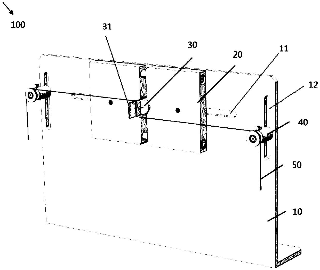
[0016] figure 1 It is a schematic diagram of the overall structure of the mechanical performance testing platform of the laser scanning vibrating mirror motor in the embodiment of the present invention.

[0017] Such as figure 1 As shown, a mechanical performance testing platform 100 of a laser scanning vibrating mirror motor in this embodiment has a mounting base 10 , a vibrating mirror motor clamping mechanism 20 , a vibrating mirror motor 30 , a pulley adjusting mechanism 40 and a thin wire 50 .

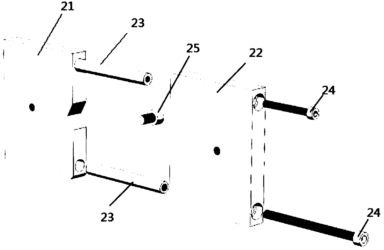
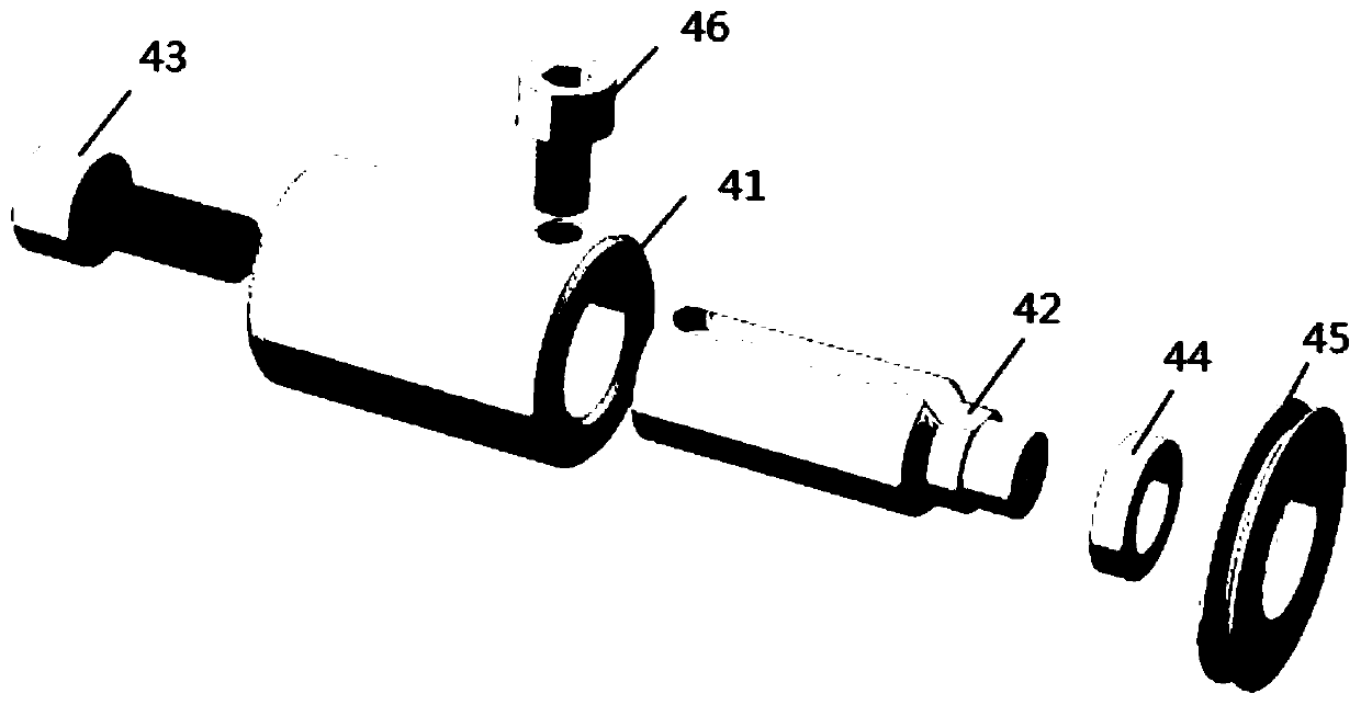
[0018] The mounting seat 10 is L-shaped, and has a horizontal bottom plate placed on the ground and a vertical plate connected to the horizontal bottom plate. A horizontal guide groove 11 is provided at the upper center of the vertical plate, and a hori...


PUM


Abstract

The invention provides a mechanical performance testing platform for a laser scanning galvanometer motor, which comprises a mounting seat, a galvanometer motor clamping mechanism, a galvanometer motor, pulley adjusting mechanisms and a thin wire, wherein the mounting seat comprises a horizontal bottom plate placed on the ground and a vertical plate connected to the horizontal bottom plate, and thevertical plate is provided with a horizontal guide groove and vertical guide grooves; the galvanometer motor clamping mechanism is mounted on the vertical plate and comprises a first clamping block and a second clamping block both provided with V-type grooves in the horizontal guide groove, guide rods arranged on the first clamping block and guide rod screws placed in the second clamping block; the galvanometer motor is clamped between the V-type grooves and the rotating shaft of the galvanometer motor is connected with a reflecting lens; the pulley adjusting mechanisms are correspondingly arranged in the vertical guide grooves, each pulley adjusting mechanism comprises a guide sleeve and a guide groove screw arranged on two side surfaces of the vertical guide groove and mutually matched,a guide column placed in the guide sleeve, a bearing arranged at the small shaft end of the guide column and a pulley arranged on the outer circle of the bearing; and the thin wire is wound on the cross section of the reflecting lens, and two free ends of the thin wire are guided out from opposite directions and are placed on the pulley.

Description

technical field [0001] The invention belongs to the field of mechanical performance testing of vibrating mirror motors, in particular to a mechanical performance testing platform of laser scanning vibrating mirror motors. Background technique [0002] The vibrating mirror motor is a special swing motor, whose rotating shaft is connected with the reflector, and the reflection angle of the laser beam is changed through the swing of the rotor to realize the scanning motion of the laser. [0003] The characteristic parameters of the vibrating mirror motor are very important to the performance evaluation of the motor and the design of the control driver. Due to its special function and structure, the general measurement method of the characteristic parameters of the rotating motor will not be suitable for the vibrating mirror motor. Especially when studying the mechanical properties of the vibrating mirror motor, it is first necessary to install and fix the vibrating mirror motor...

Claims


Application Information

Patent Timeline
Patent Type & Authority Applications(China)
IPC IPC(8): G01M13/00
CPCG01M13/00
Inventor 陈光胜周雨时
Owner UNIV OF SHANGHAI FOR SCI & TECH
Learn More