
Semiconductor material production technology equipment

A production technology, semiconductor technology, applied in the direction of metal processing equipment, grinding/polishing equipment, grinding/polishing safety devices, etc., can solve problems such as outward splashing, wear and unevenness of internal components of the polishing machine, and achieve damage Effect

Inactive Publication Date: 2019-08-23
刘良国
View PDF0 Cites 2 Cited by
  • Summary
  • Abstract
  • Description
  • Claims
  • Application Information

AI Technical Summary

Problems solved by technology

[0002] After the semiconductor production is completed, due to the local unevenness on the surface, the semiconductor needs to be further polished. , when the residual material is separated from the semiconductor, it will splash outward under the action of centripetal force. Therefore, it is necessary to design a semiconductor production equipment that prevents the residual material from splashing. The current semiconductor material production technology equipment has the following defects:
[0003] The traditional solution is to set up a cover on the outside of the polishing machine to cover the polishing machine, but this way is easy to cause the residual material to splash and fall and deposit between the inner edge of the cover and the polishing machine due to the blocking of the cover, and the residual material will follow. The vibration generated when the polishing machine is working falls inside the polishing machine, causing the internal components of the polishing machine to wear out, and even causing the internal components of the polishing machine to be stuck

Method used


Image

  • Semiconductor material production technology equipment
  • Semiconductor material production technology equipment
  • Semiconductor material production technology equipment

Examples


Embodiment

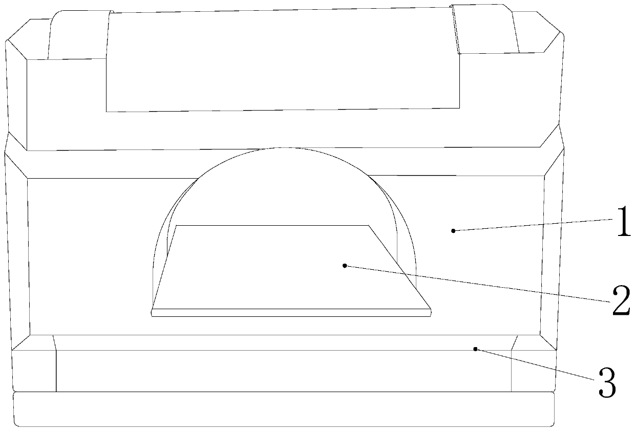
[0026] see Figure 1-Figure 6 , the present invention provides technical equipment for semiconductor material production, the structure of which includes a chip collecting device 1, a processing table 2, and a housing 3. The chip collecting device 1 is mechanically connected to the processing table 2, and the processing table 2 is arranged on the housing 3 in the center and penetrate the shell 3, the shell 3 is connected with the chip collecting device 1;

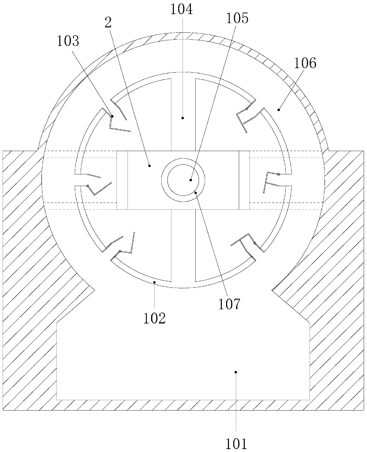
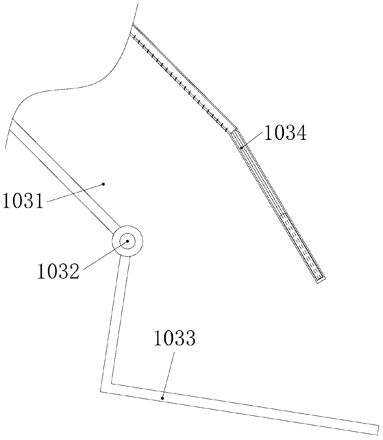
[0027] The chip collecting device 1 is composed of a chip collecting chamber 101, an annular wall plate 102, a chip feeding mechanism 103, a rotating rod 104, a central shaft 105, an annular channel 106, and a connecting shaft disk 107. The channel 106 communicates, and the annular channel 106 is connected with the annular wall plate 102. The chip feeding mechanism 103 is fixedly installed on the annular wall plate 102. There are more than four chip feeding mechanisms 103, and the The annular wall plate 102 is mechanically...


PUM


Abstract

The invention discloses semiconductor material production technology equipment. The equipment structurally comprises a chip collecting device, a machining table and a shell, wherein the chip collecting device is mechanically connected with the machining table; the machining table is arranged in the center of the shell and penetrates through the shell; and the shell is connected with the chip collecting device. The semiconductor material production technology equipment has the beneficial effects that external mechanical force is used to drive a center shaft to rotate clockwise, and a chip feeding mechanism is driven to rotate by a rotating rod, so that waste chip generated by a polishing machine enters into the chip feeding mechanism and reach an annular channel so as to achieve the purposeof collecting the waste chip; and through the different height reached by the chip feeding mechanism rotating with an annular wall plate, the size of openings between a movable plate and a fixing plate after rotating around a fixing shaft is different, and a rectangular slide block slides downward under the action of gravity to squeeze the air into a first cavity to push a rotating shifting pieceto rotate so as to assist in shifting waste chips into a chip collecting cavity to achieve the purpose of avoiding the damage of parts inside the polishing machine caused by the waste chip entering into the polishing machine.

Description

technical field [0001] The invention relates to the field of semiconductors, in particular to a technical equipment for producing semiconductor materials. Background technique [0002] After the semiconductor production is completed, due to the local unevenness on the surface, the semiconductor needs to be further polished. , when the residual material is separated from the semiconductor, it will splash outward under the action of centripetal force. Therefore, it is necessary to design a semiconductor production equipment that prevents the residual material from splashing. The current semiconductor material production technology equipment has the following defects: [0003] The traditional solution is to set up a cover on the outside of the polishing machine to cover the polishing machine, but this way is easy to cause the residual material to splash and fall and deposit between the inner edge of the cover and the polishing machine due to the blocking of the cover, and the r...

Claims


Application Information

Patent Timeline
IPC IPC(8): B24B55/06B24B55/12
CPCB24B55/06B24B55/12
Inventor 刘良国
Owner 刘良国
Learn More