
Eureka
For R&D, Eureka makes reading and utilizing patents & technical documents easy.
Eureka AIR
Designed for self-driven R&D workflows. Generate viable solutions, solve complex R&D challenges, empower your innovation with AI.

Eureka Materials
Designed for material experts only. Revolutionize your material R&D, from search, analyze, to developing new materials.

TechResearch
Generate reliable direction feasibility study reports for your R&D in just a few steps.

TechSeek
Discover and master advanced knowledge NOW. Basics, ideas, possibilities, all at once.

TechMind
As an expert in R&D Theories, TechMind can generates customized viable solutions instantly.

TechRisk
Analyze your overall solution with one click, know your potential R&D risks in advance.

TechMonitor
Get weekly tech updates, stay abreast of the latest tech innovations and key insights.
Electric ball locking device for positioning and supporting
A positioning support and electric lock technology, which is applied in the direction of workpiece clamping devices and manufacturing tools, can solve the problems of inconvenient adaptive adjustment, affecting positioning accuracy, and unbalanced force on positioning balls, and achieves simple mechanism, high transmission efficiency, The effect of force balance
- Summary
- Abstract
- Description
- Claims
- Application Information
AI Technical Summary
Problems solved by technology
Method used
Image

Examples
Embodiment 1
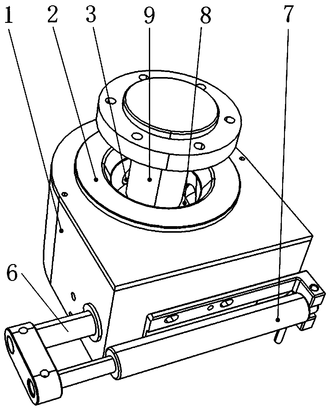
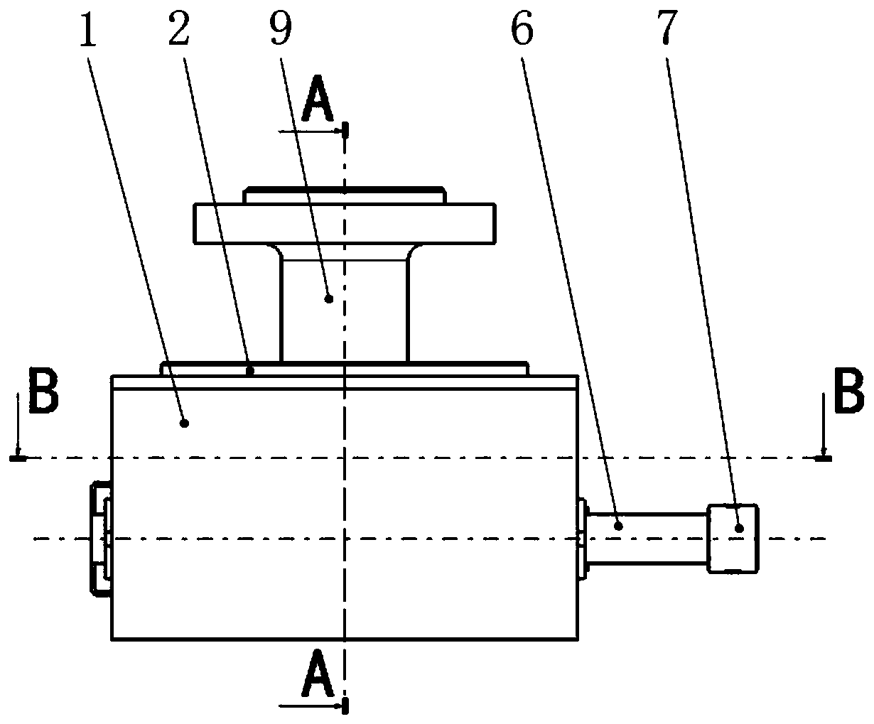
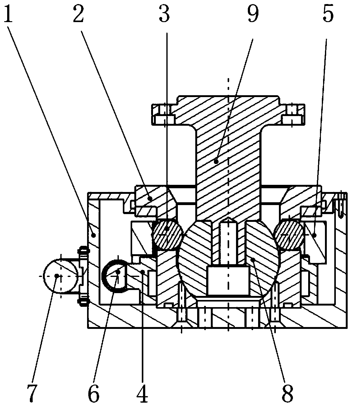
[0031] See Figure 1 to Figure 7 , the present invention has a housing 1, a ball seat 2, a clamping ball 3, an inner sleeve 5, a positioning ball 8 and a ball locking mechanism; It has a spherical groove; the clamping balls 3 are respectively placed in at least three evenly distributed circular holes on the side wall of the ball seat 2; the inner sleeve 5 is sleeved on the outside of the clamping ball 3, and the inner sleeve 5 is provided with The groove matched with the clamping ball 3, the lower end surface of the inner sleeve 5 is in contact with the ball locking mechanism;
[0032] The ball locking mechanism includes a gear 4, a rack 6 and an electric push rod 7; the gear 4 is fixedly arranged on the outer surface of the ball seat 2, and the upper end surface of the gear 4 is in contact with the inner sleeve 5; the rack 6 meshes with the gear 4, and the rack 6 is connected to the push rod working end of the electric push rod 7; the fixed end of the electric push rod 7 is ...
Embodiment 2
[0036] See Figure 8 to Figure 14 , the present embodiment is basically similar to Embodiment 1, the difference is that the ball locking mechanism includes a first bevel gear 10, a second bevel gear 11 and a servo motor 7; the first bevel gear 10 is fixedly connected to the outer surface of the ball seat 2; The inner sleeve 5 is arranged above the first bevel gear 10 ; the second bevel gear 11 meshes with the first bevel gear 10 , and the second bevel gear 11 is connected with the rotating shaft of the servo motor 7 .
[0037] An observation window 12 is arranged on the side of the housing 1, through which the internal rotation can be observed and the locking situation can be judged.
[0038] The working principle of the present invention is: when the workpiece is positioned and supported, according to the external dimensions and weight of the workpiece, the positioning rods 9 are connected at multiple positions at the bottom of the workpiece, and the device is installed at th...
PUM
 Abstract
Description
Claims
Application Information
 - R&D Engineer
- R&D Manager
- IP Professional
- Industry Leading Data Capabilities
- Powerful AI technology
- Patent DNA Extraction
Browse by: Latest US Patents, China's latest patents, Technical Efficacy Thesaurus, Application Domain, Technology Topic, Popular Technical Reports.
© 2024 PatSnap. All rights reserved.Legal|Privacy policy|Modern Slavery Act Transparency Statement|Sitemap|About US| Contact US: help@patsnap.com