Rotary knife device capable of automatically compensating

An automatic compensation and rotary knife technology, applied in metal processing and other directions, can solve the problems of manual adjustment of cutting blades, and achieve the effect of automatically compensating for blade gap, improving utilization rate and improving work efficiency.

Pending Publication Date: 2019-08-23
CHONGQING CHANGZHENG HEAVY IND
View PDF0 Cites 0 Cited by
  • Summary
  • Abstract
  • Description
  • Claims
  • Application Information

AI Technical Summary

Problems solved by technology

[0003] The purpose of the present invention is to realize the automatic compensation of the cutting blade after it is worn out, aiming at the problem in the prior art that the cutting blade needs to be manually adjusted after being worn out.

Method used


Image

  • Rotary knife device capable of automatically compensating
  • Rotary knife device capable of automatically compensating
  • Rotary knife device capable of automatically compensating

Examples


Embodiment 1

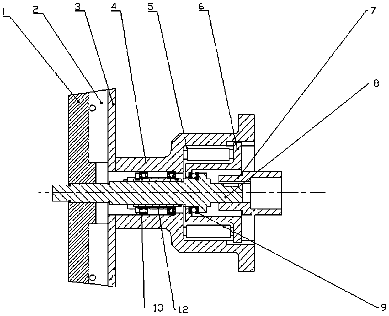
[0029] This embodiment provides a rotary knife device capable of automatic compensation, including a knife handle 1, a blade 2, a cutter head 3, a mounting seat 4, a thrust member 5, a bearing seat 6, a coupling 7, a rotating shaft 8, and a thrust ball bearing 9. Sleeve 12, deep groove ball bearing 13.

[0030] Such as figure 1 As shown in the schematic diagram of the structure of Embodiment 1 of the present invention, one end of the rotating shaft 8 is provided with a handle 1, and the handle 1 can be fixed on the front end of the rotating shaft 8 by threaded connection, and several blades 2 are arranged on the handle 1. The other end of the shaft 8 is a shaft coupling 7, and the shaft coupling 7 provides rotational power to make the blade 2 rotate and work.

[0031] The cutter head 3 and the mounting seat 4 are fixed on the machine tool, and the cutter head 3 and the blade 2 are next to each other.

[0032] There is a sleeve 12 in the middle of the rotating shaft 8, and de...

Embodiment 2

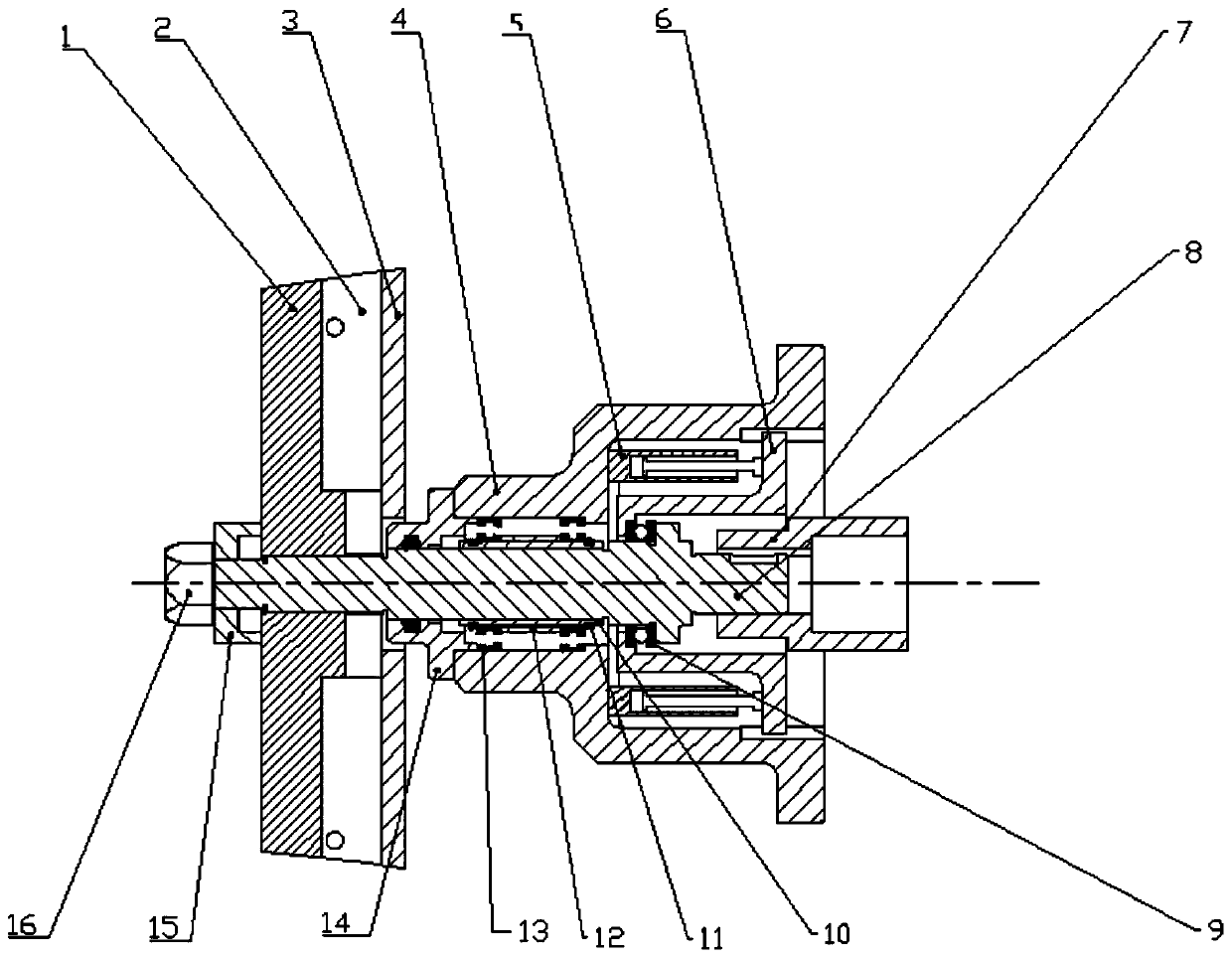
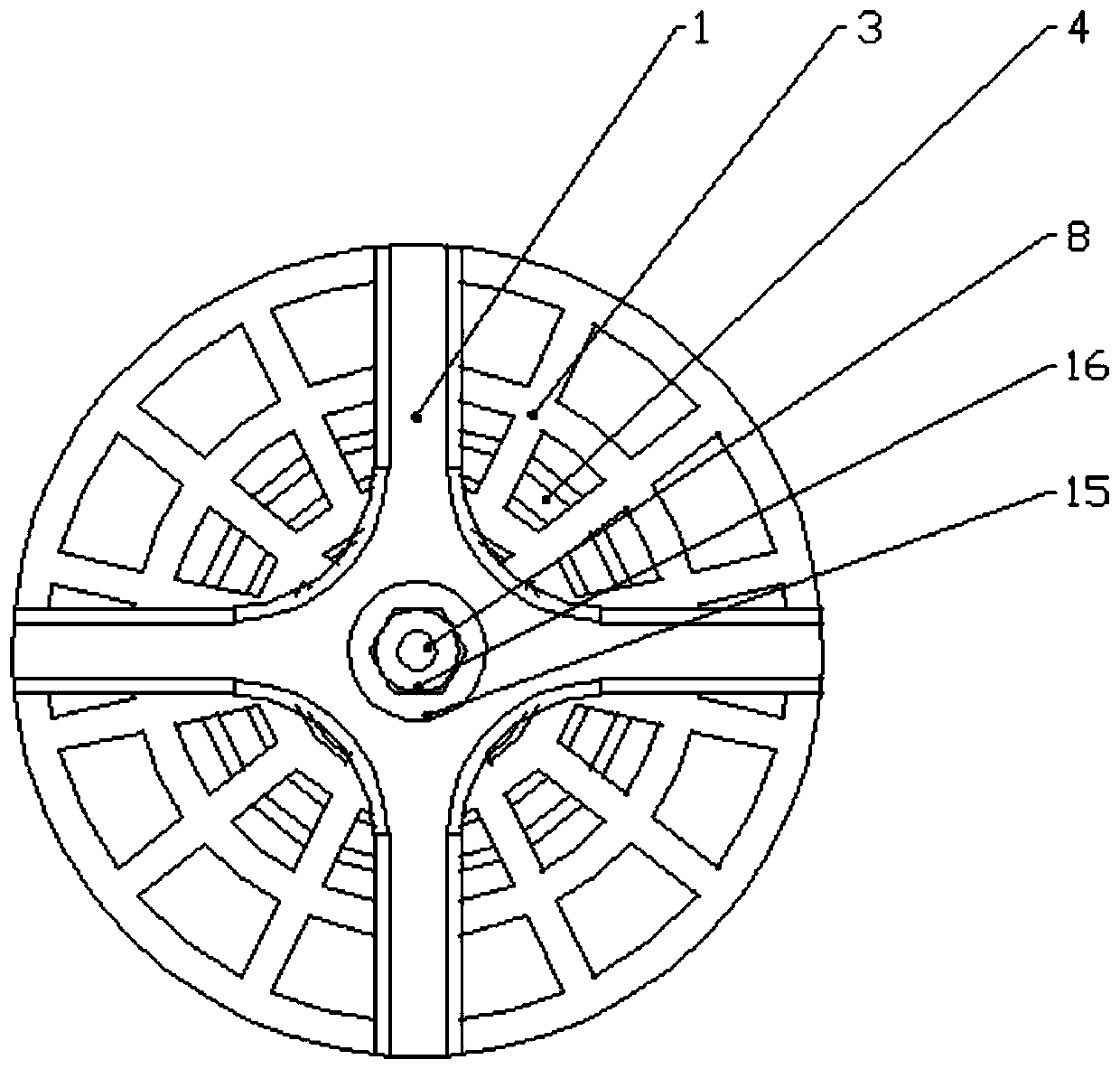
[0038] Embodiment 2 provides a rotary knife device capable of automatic compensation, including a knife handle 1, a blade 2, a cutter head 3, a mounting seat 4, a thrust member 5, a bearing seat 6, a coupling 7, a rotating shaft 8, and a thrust ball bearing 9, shaft sleeve, 10, thrust ring 11, sleeve 12, deep groove ball bearing 13, dustproof cover 14, nut sleeve 15, fixed nut 16.

[0039] Such as figure 2 As shown in the schematic diagram of the structure of Embodiment 2 of the present invention, one end of the rotating shaft 8 is provided with a knife handle 1, and the knife handle 1 can be fixed on the front end of the rotating shaft 8 through threaded connection. The other end of the shaft 8 is a shaft coupling 7, and the shaft coupling 7 provides rotational power to make the blade 2 rotate and work.

[0040] The cutter head 3 and the mounting seat 4 are fixed on the machine tool, and the cutter head 3 and the blade 2 are next to each other.

[0041] The knife handle 1 ...


PUM


Abstract

The invention relates to the field of cutting blades, in particular to a rotary knife device capable of automatically compensating. The rotary knife comprises a blade, a knife flywheel, a mounting base and a bearing base, wherein the mounting base and the knife flywheel are fixedly arranged; the mounting base and the bearing base are connected to a rotary shaft through bearings; the bearing base and the mounting base define a cavity; at least two thrust parts are arranged in the cavity for pushing the bearing base; and the bearing base drives the rotary shaft to move in a direction away from the mounting base, so that the blade is pushed to perform automatic compensation on the knife flywheel, and therefore, problems such as poor cutting quality and part damages caused by gaps generated byblade cutting abrasion are solved.

Description

technical field [0001] The invention relates to the field of cutting blades, in particular to a rotary knife device capable of automatic compensation. Background technique [0002] In the existing cutting equipment, it includes a blade and a cutter head. The blade is a movable knife, and the cutter head is a fixed knife. ; The blade rotates relative to the cutter head to form a cutting of the material. During the cutting process of the movable blade, the edge of the knife that contacts the cutter head will be worn accordingly. After the movable blade is worn, a gap will be formed between the movable blade and the cutter head, which will affect the cutting effect and the life of the blade. In the prior art, after the cutting blade wears, manual adjustment is required to compensate for the wear. This method of compensating wear is not only cumbersome to operate, but also needs to be carried out in a shutdown state to ensure safety; therefore, there are defects that the equip...

Claims


Application Information

Patent Timeline
Patent Type & Authority Applications(China)
IPC IPC(8): B26D1/25B26D5/12B26D7/26
CPCB26D1/25B26D5/12B26D7/2628
Inventor 李沛海汪健吴印张明明彭期伟
Owner CHONGQING CHANGZHENG HEAVY IND
Why Eureka
Try Eureka