Novel flow guiding device for screw propeller

A technology of diversion devices and propellers, which is applied in transportation and packaging, ship propulsion, ship parts, etc. It can solve the problems that underwater water plants and other debris are easy to get stuck in the pipe, affecting the normal navigation of the ship, and the ship's navigation resistance is large, etc., to achieve Reduce the separation of water bodies, improve the efficiency of the propeller, and the effect of uniform inflow

Active Publication Date: 2019-08-23
HANGZHOU DIANZI UNIV +1
View PDF7 Cites 0 Cited by
  • Summary
  • Abstract
  • Description
  • Claims
  • Application Information

AI Technical Summary

Problems solved by technology

The diameter is slightly larger than the diameter of the propeller, so that underwater aquatic plants and other debris are easy to get stuck in the tube, and if there is a hard object colliding and deforming, the blade tip will collide with the inner wall of the tube, which will affect the normal navigation of the ship
The side section of the pipe is similar to a platform shape, which makes the incoming flow unstable, the energy saving efficiency is not high, and the ship's navigation resistance is relatively large.

Method used


Image

  • Novel flow guiding device for screw propeller
  • Novel flow guiding device for screw propeller
  • Novel flow guiding device for screw propeller

Examples


Embodiment 1

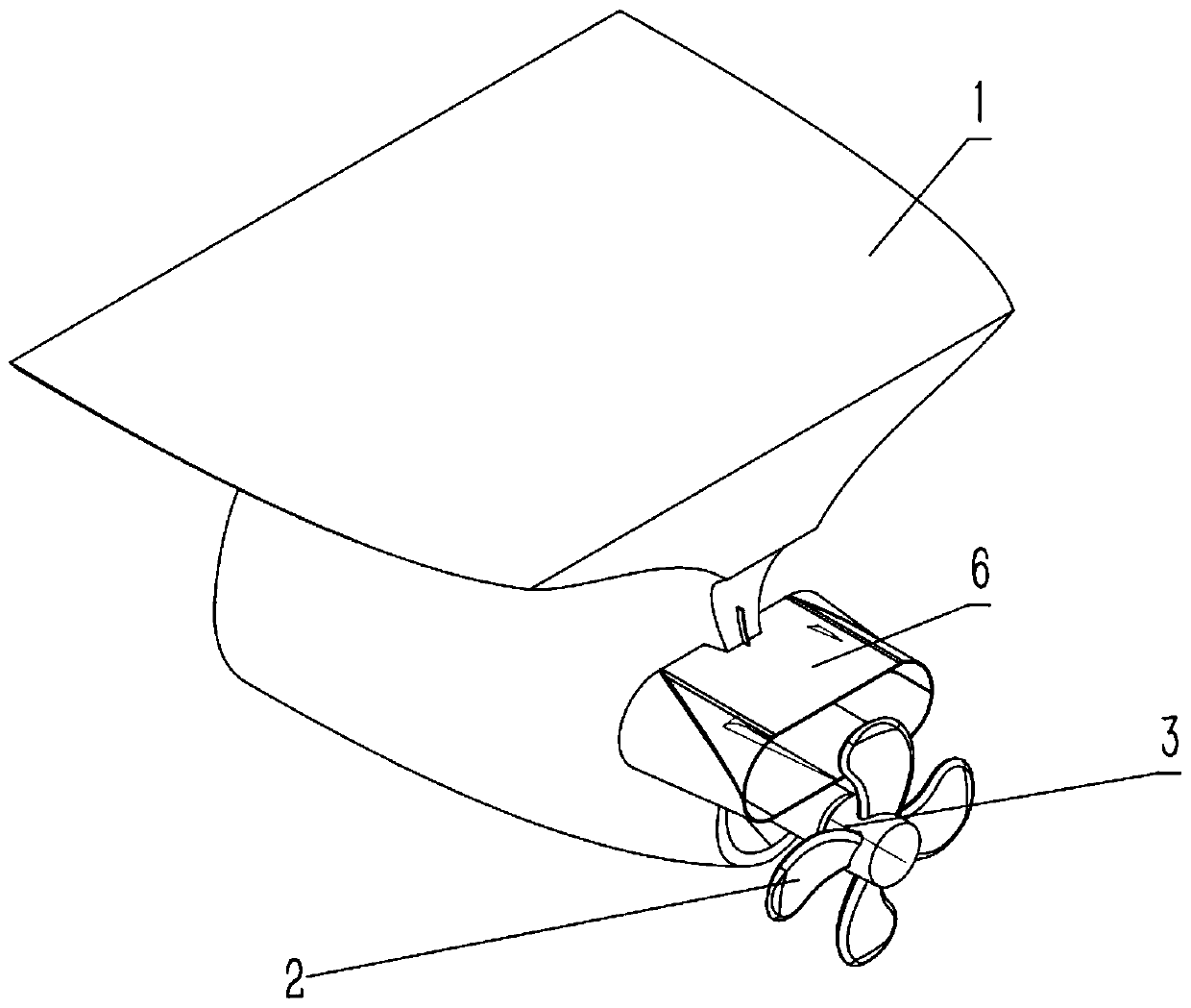
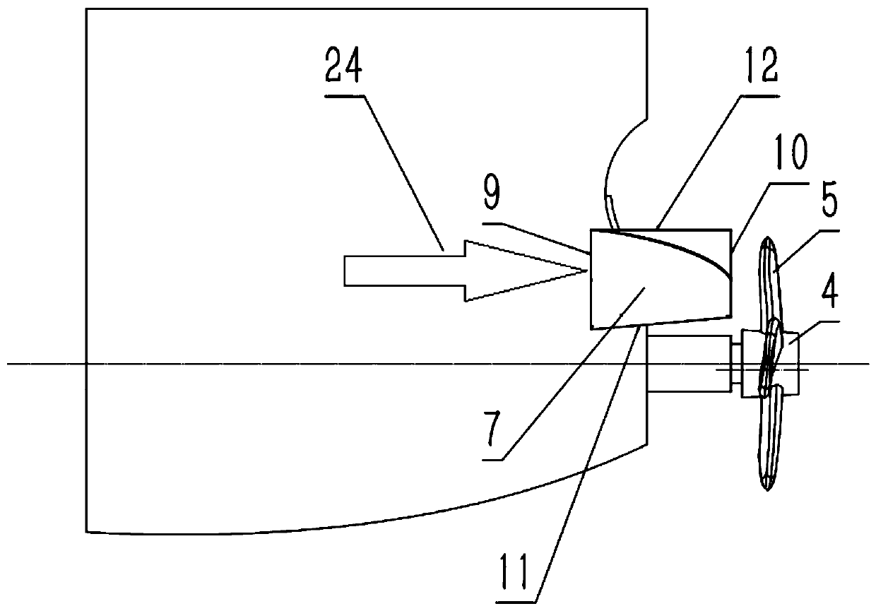
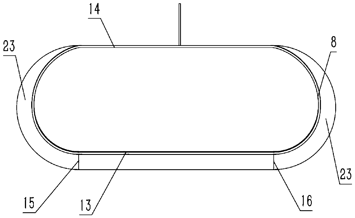
[0018] Example 1, such as Figure 1~7 As shown, a novel propeller deflector includes a hull 1 and a propeller 2 on the rear side of the hull. The upper side of the propeller 2 is provided with a guide tube 6. The guide tube 6 includes a front end surface, a rear end surface, an upper end surface, and a lower end surface. , left and right sides 23, the two ends of the cross section of the front end of the draft tube 6 are semicircular, straight sides are between the semicircular sections of the front end of the draft tube, the cross-sectional shape of the rear end of the draft tube 6 is the same as that of the front end of the draft tube The shape of the surface is the same, the cross-sectional area of ​​the rear end face of the draft tube 6 is less than the cross-sectional area of ​​the front end face of the draft tube 6, the upper end surface of the draft tube 6 is a horizontal plane, and the lower end surface of the draft tube 6 and the outer walls of the left and right sides...


PUM


Abstract

The invention belongs to a novel flow guiding device for a screw propeller. The novel flow guiding device comprises a ship body and the screw propeller, wherein a flow guiding tube is arranged on theupper side of the screw propeller; the two ends of the cross section of the front end face of the flow guiding tube; a straight side is formed between a semicircle of the cross section of the front end face of the flow guiding tube; the upper end face of the flow guiding tube is a horizontal plane; inclination angles are arranged on the lower end face, the left side face and the right side face ofthe flow guiding tube; flowing lines of the inner walls of the lower end face, the left side face and the right side face firstly flow from the front end face, gradually go upwards to the topmost point and then gradually go downwards to the rear end face; and when the flowing line of the inner wall of the lower end face flows to the rear end face, the curvature of the flowing line is 0, and the curvatures of the topmost points of the flowing lines of the inner walls of the left and right side faces are gradually reduced to 0 from the beginning of the lower end face to the end of the upper endface. According to the novel flow guiding device for the screw propeller disclosed by the invention, the size and the shape of the flow guiding tube are reduced, and the flow guiding device is arranged in front of the screw propeller, so that flow incoming of the screw propeller is more uniform, the resistance of the flow guiding tube is reduced, additional thrust is increased, the separation phenomenon of a tail-part water body of the ship body is reduced, and the working efficiency of the screw propeller is improved; and moreover, the flow guiding device disclosed by the invention has the advantages of being simple and firm in structure, reduced in energy and reduced in resistance.

Description

technical field [0001] The invention belongs to the technical field of ships, and in particular relates to a novel propeller deflector. Background technique [0002] At this stage, with the development of the new normal economy, the shipping industry is developing rapidly, but the energy consumption of the traditional shipping industry is huge, and this high energy consumption makes the cost of shipping transportation remain high. Therefore, the development of ship energy-saving technology has attracted much attention, and it is an effective method to install a guide tube for the propeller that provides thrust to the ship to achieve the purpose of saving energy and reducing consumption. The traditional guide tube is installed directly in front of the propeller, which increases the turning radius of the ship, and deteriorates the turning performance and low-speed rudder effect of the ship. The diameter is slightly larger than the diameter of the propeller, so that underwater...

Claims


Application Information

Patent Timeline
Patent Type & Authority Applications(China)
IPC IPC(8): B63H5/16
CPCB63H5/16
Inventor 田晓庆邵汉东潘玉鹏潘华辰吕明
Owner HANGZHOU DIANZI UNIV
Why Eureka
Try Eureka