A small electromagnetic launcher

A launching device and electromagnetic technology, applied in the field of electromagnetic weapons, can solve problems such as complex mechanical structure and automatic process, casualties, and easy exposure of its own position, and achieve the effects of simplified internal structure, simple mechanical movement, and simple launch circuit

Inactive Publication Date: 2022-01-11
NANJING UNIV OF SCI & TECH
View PDF7 Cites 0 Cited by
  • Summary
  • Abstract
  • Description
  • Claims
  • Application Information

AI Technical Summary

Problems solved by technology

[0002] At present, our country's civilian police often lack suitable weapons to deal with some public security and anti-riot issues, so they desperately need a firearm dedicated to anti-riot to reduce unnecessary casualties
[0003] However, the existing non-lethal firearms used for anti-riot generally use chemical energy (gunpowder) to launch, which is more powerful in close-range combat and may cause permanent damage to the target.
Such traditional firearms mostly use cased fixed-load bullets, and their mechanical structure needs to complete the process of shell extraction and ejection, and the mechanical structure and automatic process are relatively complicated.
In addition, fixed-loaded bullets can hardly achieve power controllability. For different anti-riot situations, it is difficult to switch their power as soon as possible, which often easily causes unnecessary casualties. Traditional fixed-loaded bullets contain gunpowder and shell casings, and single-person carry bullets The amount is still not limited, if it falls into the hands of criminals accidentally, it will easily endanger social security
And the firearms that use gunpowder to launch projectiles are often accompanied by muzzle flames, noise and smoke when firing, which can easily expose their position and attract hostile targets to attack

Method used


Image

  • A small electromagnetic launcher
  • A small electromagnetic launcher
  • A small electromagnetic launcher

Examples


Embodiment Construction

[0018] The present invention will be further introduced below in conjunction with the accompanying drawings and specific embodiments.

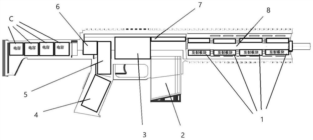
[0019] to combine figure 1 , a small electromagnetic launching device of the present invention, comprising a power supply module, a plurality of launching modules 1 connected in series, a control module 7, and a bomb supply module 2;

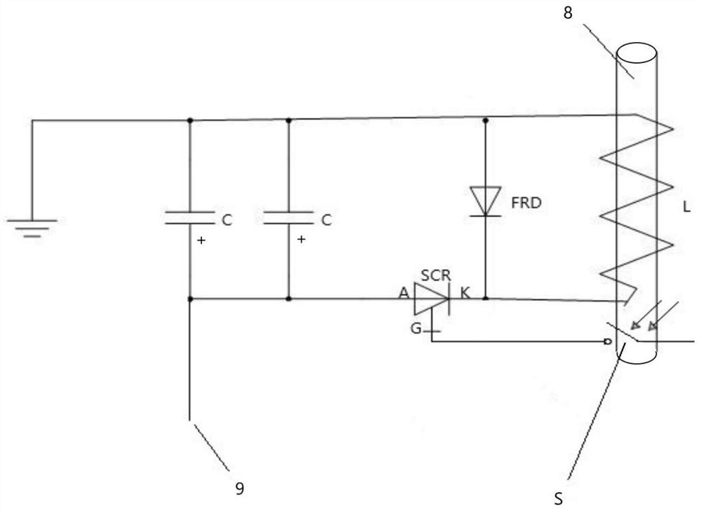
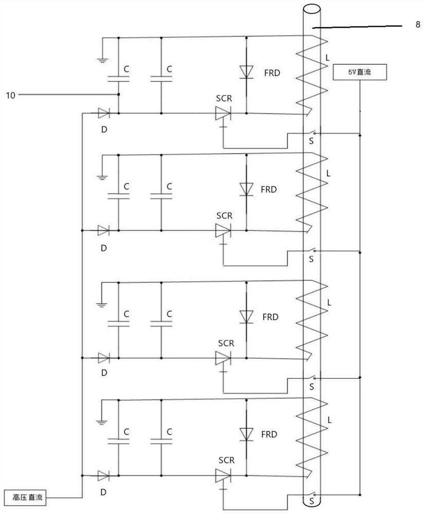
[0020] to combine figure 2 , the transmitting module includes a capacitor C, a fast recovery diode FRD, a thyristor SCR, a coil L and a photoelectric switch S; the capacitor C is connected in parallel with the fast recovery diode FRD and the coil L; the cathode of the fast recovery diode FRD, A thyristor SCR is connected between the current inlet port of the coil L and the anode of the capacitor C; the K pole of the thyristor SCR is connected to the cathode of the fast recovery diode FRD and the current inlet port of the coil L, and the A pole of the thyristor SCR is connected to The anode of the capacitor C,...


PUM


Abstract

The invention discloses a small-sized electromagnetic launching device, which includes a power supply module, a plurality of launching modules connected in series, a control module, and a bomb supply module for supplying power to other modules; the launching module includes a capacitor, a fast recovery diode, a thyristor, a coil and Photoelectric switch; the capacitor is connected in parallel with the fast recovery diode and the coil; the cathode of the fast recovery diode, the coil current inlet end are connected to the anode of the capacitor with a thyristor; the K pole of the thyristor is connected to the cathode of the fast recovery diode and the coil current inlet end, and the A pole is connected The anode of the capacitor, the G pole is connected to the photoelectric switch; the cathode of the capacitor is grounded, and the anode is connected to the power supply module; the capacitor is provided with a voltage detection port and a charging port; the voltage detection port is connected to the control module; the charging port is connected to the power supply module through the first relay; the coil Wrapped outside the gun barrel; the bomb feeding module is connected with the control module through the second relay; the photoelectric switch is arranged at the emitting end of the gun barrel; the control module controls the relay on and off. The invention can realize the miniaturization of the transmitting device.

Description

technical field [0001] The invention belongs to the field of electromagnetic weapons, in particular to a small electromagnetic launching device. Background technique [0002] At present, our country's civilian police often lack suitable weapons when dealing with some public security and anti-riot issues, so they desperately need a firearm dedicated to anti-riot to reduce unnecessary casualties. [0003] However, the existing non-lethal firearms used for anti-riot generally adopt chemical energy (gunpowder) to launch, which is powerful in close combat and may cause permanent damage to the target. Such traditional firearms mostly adopt cased fixed-load bullets, and its mechanical structure also needs to complete the process of extracting and ejecting the shell, and the mechanical structure and automatic process are relatively complicated. In addition, fixed-loaded bullets can hardly achieve power controllability. For different anti-riot situations, it is difficult to switch t...

Claims


Application Information

Patent Timeline
Patent Type & Authority Patents(China)
IPC IPC(8): F41B6/00
CPCF41B6/003
Inventor 张雯浩孙新亮龚睿温垚珂宋焦徐诚王亚平
Owner NANJING UNIV OF SCI & TECH
Why Eureka
Try Eureka