
Temperature liquid level monitoring device for liquid immersion power equipment

A technology for power equipment and liquid level monitoring, applied in measuring devices, instruments, etc., can solve problems such as inability to perform pre-intervention, unscientific, untimely, etc., to ensure the quality of power supply, intelligent asset management, and achieve the effect of asset management

Pending Publication Date: 2019-08-23
苏州翰为电气科技有限公司
View PDF0 Cites 0 Cited by
  • Summary
  • Abstract
  • Description
  • Claims
  • Application Information

AI Technical Summary

Problems solved by technology

[0003] At present, the tubular liquid level and pressure release devices used in power equipment, especially liquid-immersed distribution transformers, only have two functions of external liquid level observation and pressure release, and cannot realize real-time monitoring of the internal temperature of power equipment. It is also impossible to carry out remote signaling, remote measurement and remote control of the liquid temperature and the position of the internal insulating liquid level. Therefore, when the initial signs of problems in the electrical equipment cannot be predicted in advance, let alone pre-intervention, the liquid level can only be observed through frequent on-site inspections situation, to judge the status of power equipment; this is neither scientific nor accurate nor timely
[0004] Moreover, it is impossible to realize intelligent power supply quality management with the current tube-type liquid level and pressure release device
The current method is basically only when the power equipment fails and the pressure release device operates, the operation of the power equipment can be canceled through the on-site personnel alarm. This is often the after-knowledge and post-processing after the failure, which has actually caused huge losses in power supply quality and assets.

Method used


Image

  • Temperature liquid level monitoring device for liquid immersion power equipment
  • Temperature liquid level monitoring device for liquid immersion power equipment
  • Temperature liquid level monitoring device for liquid immersion power equipment

Examples


Embodiment 1

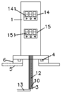
[0032] Embodiment one: if figure 1 As shown, a temperature and liquid level monitoring device for liquid immersion power equipment does not include a temperature data transmission device 11, a liquid level position data transmission device 16, a pressure release device 7, a float 8, a transparent tube 9 and an inspection window.

Embodiment 2

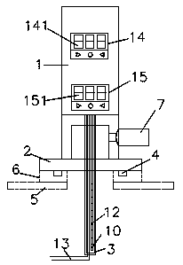
[0033] Embodiment two: if figure 2 As shown, a temperature and liquid level monitoring device for liquid immersion power equipment does not include a temperature data transmission device 11, a liquid level position data transmission device 16, a float 8, a transparent tube 9 and an inspection window.

Embodiment 3

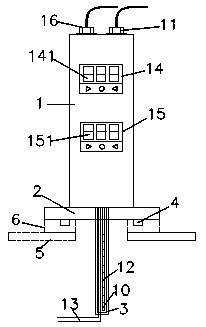
[0034] Embodiment three: as image 3 As shown, a temperature and liquid level monitoring device for liquid immersion power equipment does not include a pressure release device 7, a float 8, a transparent tube 9 and an inspection window.


PUM


Abstract

The invention discloses a temperature liquid level monitoring device for liquid immersion power equipment, comprising a pipe body and a thin pipe body, wherein a temperature sensor and a liquid levelposition data sensor are arranged in the thin pipe body, the temperature sensor is connected with a temperature monitoring system arranged in the pipe body, and the liquid level position data sensor is connected with a liquid level position detecting system arranged in the pipe body; the temperature monitoring system is connected in parallel with a liquid level position; an inspection window is arranged on a side face of the pipe body, or a transparent pipe is arranged below the pipe body; and a pressure release device connected with the thin pipe body in the pipe body is horizontally installed on an outer side position of the pipe body. The temperature liquid level monitoring device for liquid immersion power equipment has temperature monitoring, liquid level detection, liquid level observation and pressure release functions, can understand the online state of the power equipment in real time, predict the failure of the power equipment, and provide reference for intervening the operation of the power equipment in advance, so that the power supply quality can be ensured, and intelligent asset management is achieved.

Description

technical field [0001] The invention relates to the field of power equipment manufacturing, in particular to a temperature and liquid level monitoring device for liquid immersion power equipment. Background technique [0002] On power equipment, such as transformers and reactors, it has become a trend to realize the ubiquitous Internet of Things. Real-time monitoring of power equipment can ensure that the power equipment is in a controllable state, thereby improving the quality of power supply. Intelligent upgrading of accessories used in power equipment is an important means to achieve the above goals. [0003] At present, the tubular liquid level and pressure release devices used in power equipment, especially liquid-immersed distribution transformers, only have two functions of external liquid level observation and pressure release, and cannot realize real-time monitoring of the internal temperature of power equipment. It is also impossible to carry out remote signaling,...

Claims


Application Information

Patent Timeline
IPC IPC(8): G01D21/02
CPCG01D21/02
Inventor 韩宝家韩佳平韩放韩宝华韩明鉴
Owner 苏州翰为电气科技有限公司
Learn More