A burn-in system for sending and receiving components

A component and aging technology, which is applied in the field of microwave components and active phased array antennas, can solve the problems of limited application range and achieve the effect of improving reliability

Active Publication Date: 2021-08-17
SHANGHAI SPACEFLIGHT ELECTRONICS & COMM EQUIP RES INST
View PDF7 Cites 0 Cited by
  • Summary
  • Abstract
  • Description
  • Claims
  • Application Information

AI Technical Summary

Problems solved by technology

This burn-in system is suitable for high-power power supply modules, and does not involve high-power microwave products, and its application range is limited

Method used


Image

  • A burn-in system for sending and receiving components
  • A burn-in system for sending and receiving components

Examples


Embodiment Construction

[0021] The technical solution in this application will be described below with reference to the accompanying drawings.

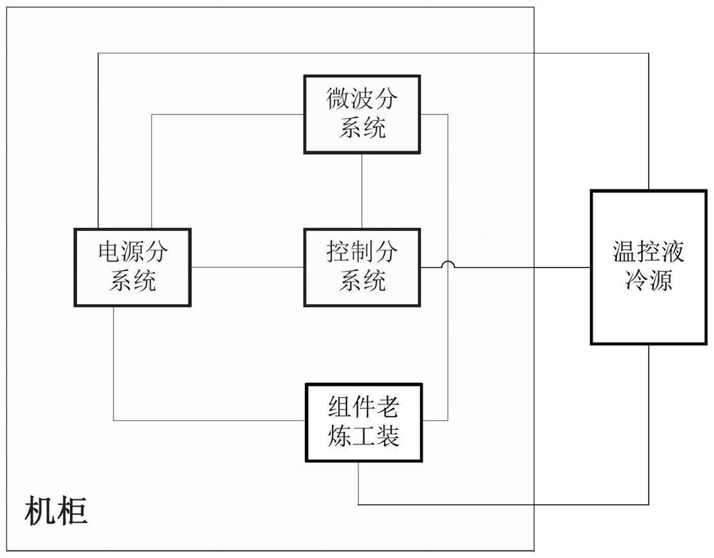
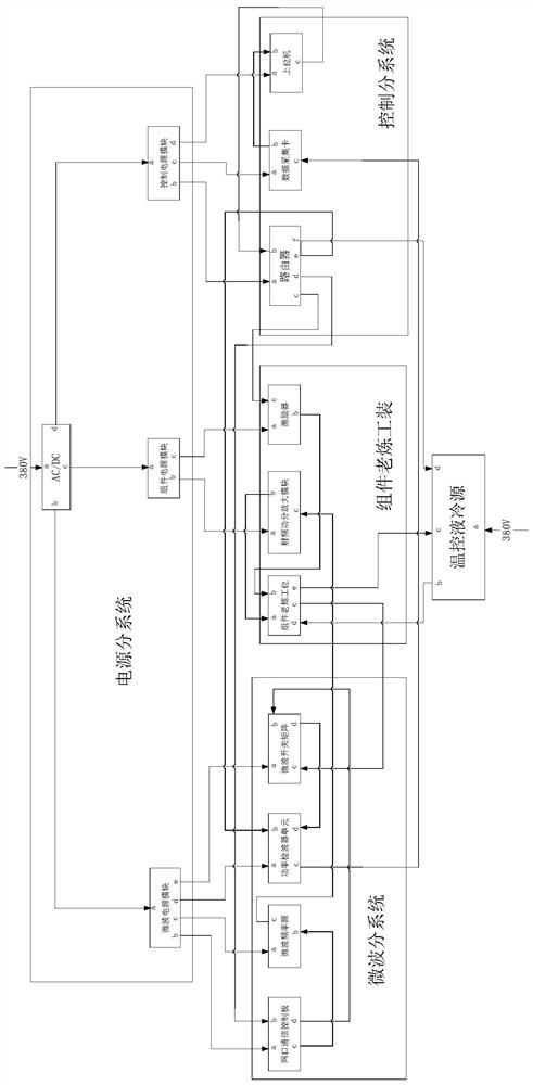
[0022] as attachedfigure 1 As shown, it is a structural block diagram of a aging system for TR components provided by an embodiment of the present invention. The structural block diagram of the aging system includes: a cabinet and a temperature-controlled liquid cooling source, wherein the cabinet includes a power subsystem , microwave subsystem, control subsystem, component aging tooling;

[0023] The power supply subsystem is respectively connected with the microwave subsystem, control subsystem, component burn-in tooling and temperature-controlled liquid cooling source for power supply of each subsystem;

[0024] The control subsystem is respectively connected with the component aging tooling, the microwave subsystem and the temperature-controlled liquid cooling source. The control subsystem is used to set the working parameters of the TR component and se...


PUM


Abstract

This application provides an aging system for TR components, including: a cabinet and a temperature-controlled liquid cooling source, wherein the cabinet includes a power subsystem, a microwave subsystem, a control subsystem, and component aging tools; The power supply subsystem is respectively connected with the microwave subsystem, the control subsystem, the component aging tooling and the temperature-controlled liquid cooling source; the control subsystem is respectively connected with the component aging tooling, the microwave The subsystem is connected to the temperature-controlled liquid cooling source; the component aging tooling is respectively connected to the microwave subsystem and the temperature-controlled liquid cooling source; the microwave subsystem is respectively connected to the control subsystem and the Component aging tooling connection; the temperature-controlled liquid cooling source is an independent refrigeration unit, and the temperature-controlled liquid cooling source is placed outside the cabinet to control the temperature of the aging system.

Description

technical field [0001] The present application relates to the technical field of microwave components and active phased array antennas, and more specifically, relates to a burn-in system for transmitting and receiving components. Background technique [0002] Burn-in is a method commonly used in engineering to eliminate early failure products and improve system reliability. Usually, after a manufacturer produces a batch of products, due to various uncertain factors, the reliability of each component in the same batch of products will be different. In order to ensure the quality of the products submitted to the users, the manufacturer will season the components before the product packaging leaves the factory, that is, to exert a certain stress on the components within a certain period of time, such as current, voltage, temperature, etc., and usually high Due to its normal use stress, some defective products are eliminated to ensure the quality of the ex-factory products. ...

Claims


Application Information

Patent Timeline
Patent Type & Authority Patents(China)
IPC IPC(8): G01R31/00G01R31/28
CPCG01R31/003G01R31/2822
Inventor 涂振斌杨晶晶张红英李尊良张鑫裴陈凯张理正雒寒冰雷鸥
Owner SHANGHAI SPACEFLIGHT ELECTRONICS & COMM EQUIP RES INST
Why Eureka
Try Eureka