Shaft-in-shaft device of twinning machine

A twisted pair machine, shaft device technology, applied in the direction of transmission, transmission parts, conductor/cable supply device, etc., can solve the problems of occupying operating space, cable winding, etc., to prevent the space occupation of the twisting work area. Effect

Pending Publication Date: 2019-08-23
GUANGZHOU HONGHUI ELECTRICIAN & MACHINERY
View PDF0 Cites 0 Cited by
  • Summary
  • Abstract
  • Description
  • Claims
  • Application Information

AI Technical Summary

Problems solved by technology

However, installing the driver in the twisting work area will cause problems such as occupying the operating space, and the cables are easily entangled with the driver, causing failures and other problems.
[0004] In the existing twisting machines on the market, there has not yet appeared to overcome the occupation of the guide wheel and transmit the power of two different driving parts in the outer area to the coaxial pay-off device and twisting bow of the input shaft, so the existing There is still a problem in the technology that cannot overcome the occupation of the guide wheel and transmit the power of two different driving parts to the two coaxial input shafts

Method used


Image

  • Shaft-in-shaft device of twinning machine

Examples


Embodiment

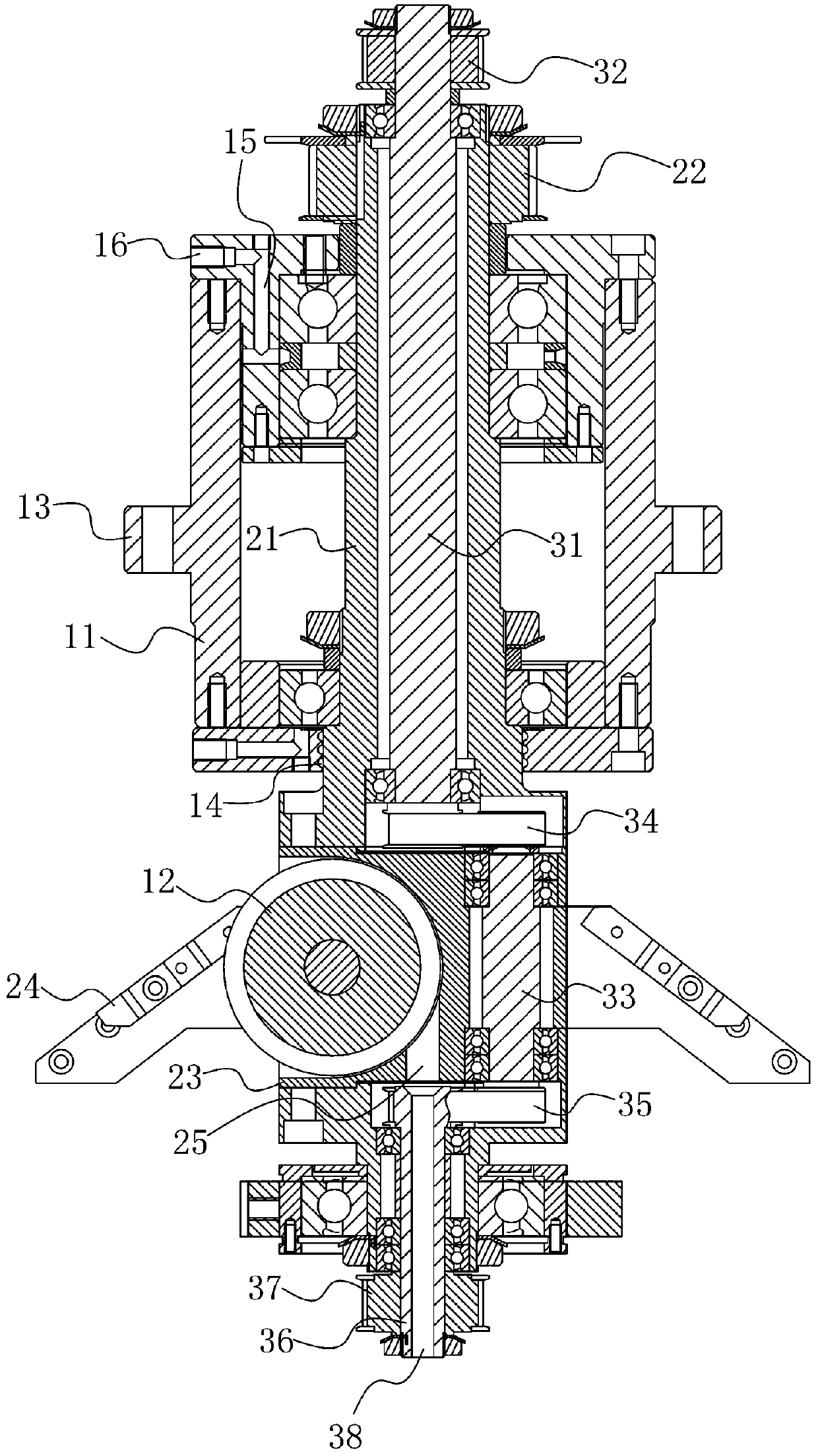
[0024] A shaft device of a twisted pair machine, such as figure 1 As shown, it includes a housing 11, a first transmission component and a second transmission component;

[0025] The first transmission assembly includes a transmission sleeve 21 and an output sleeve 23. The transmission sleeve 21 is provided with a first power input end 22. The transmission sleeve 21 and the output sleeve 23 are fixedly connected and coaxially arranged. The housing 11 is sleeved outside the transmission sleeve 21 and It is rotatably connected with the transmission sleeve 21, the output sleeve 23 is rotatably connected with a guide wheel 12, the guide wheel 12 is perpendicular to the output sleeve 23, and the output sleeve 23 is fixedly provided with a twisted bow connection end 24;

[0026] The second transmission assembly includes a transmission shaft 31, a connecting shaft 33 and an output shaft 36. The transmission shaft 31 is provided with a second power input end 32. The transmission shaft 31 i...


PUM


Abstract

The invention relates to the technical field of transmission devices, in particular to a shaft-in-shaft device of a twinning machine. The device solves the problem that the power of two different driving parts cannot be transmitted to two coaxial input shafts due to the occupation of a guide wheel in the prior art. According to the technical scheme of the invention, the device comprises a shell, afirst transmission assembly and a second transmission assembly. The first transmission assembly comprises a transmission sleeve and an output sleeve. The output sleeve is rotationally connected witha guide wheel. The output sleeve is fixedly provided with a twisting bow connecting end. The second transmission assembly comprises a transmission shaft, a connecting shaft and an output shaft. The transmission shaft is located in the transmission sleeve. The connecting shaft is located in the output sleeve. One end of the output shaft is located in the output sleeve. One end of the connecting shaft is connected with the transmission shaft through a first transmission piece. The other end of the connecting shaft is connected with the output shaft through a second transmission piece. The outputshaft is provided with a pay-off unit connecting end. According to the invention, the problem that the power of two different driving parts cannot be transmitted to two coaxial input shafts due to the occupation of the guide wheel in the prior art can be overcome.

Description

Technical field [0001] The invention relates to the technical field of transmission devices, in particular to a shaft center shaft device of a twisted pair machine. Background technique [0002] Twisted-pair machine is a kind of equipment used for twisting cables, including frame, driving shaft, pay-off device, guide wheel and twisting bow. The twisting bow is fixed with the driving shaft, and the twisting bow can be rotated on the frame. In the process of rotating, it surrounds the pay-off device, the guide wheel is tangent to the axis line of the driving shaft, and the driving shaft is provided with a thread passing hole. There are at least 2 cables in the pay-off device. The cables pass through the wire hole and are wound on the guide wheel. The angle of the cable is adjusted by the guide wheel to make the cable pass through the twisted bow, and the twisted bow drives during the rotation. The cables are rotated, so that the cables are twisted around each other, realizing the ...

Claims


Application Information

Patent Timeline
Patent Type & Authority Applications(China)
IPC IPC(8): H01B13/00H01B13/02F16H57/00F16H7/02
CPCF16H7/023F16H57/0018H01B13/0003H01B13/0207H01B13/0235H01B13/0285
Inventor 项泽鸿赵光辉何邦庆汪顺安
Owner GUANGZHOU HONGHUI ELECTRICIAN & MACHINERY
Why Eureka
Try Eureka