Rail mounting device and method for fixing rails to reinforced concrete railway sleeper

A technology for reinforcing concrete and installing devices, which is applied in the direction of fixing rails, rail fixers, railway fixing devices, etc., can solve the problems of increased cost, expensive manufacturing of rail clips, and the need for substrates.

Inactive Publication Date: 2019-08-23
HR SYST HUNGARY ZRT
View PDF16 Cites 0 Cited by
  • Summary
  • Abstract
  • Description
  • Claims
  • Application Information

AI Technical Summary

Problems solved by technology

The main disadvantage of these solutions is that, due to their special shape, rail clips are expensive to manufacture and they require a base plate, which further increases the cost

Method used


Image

  • Rail mounting device and method for fixing rails to reinforced concrete railway sleeper
  • Rail mounting device and method for fixing rails to reinforced concrete railway sleeper
  • Rail mounting device and method for fixing rails to reinforced concrete railway sleeper

Examples


Embodiment Construction

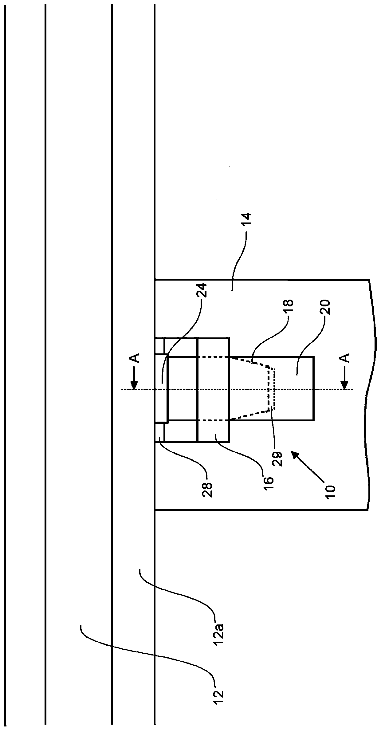
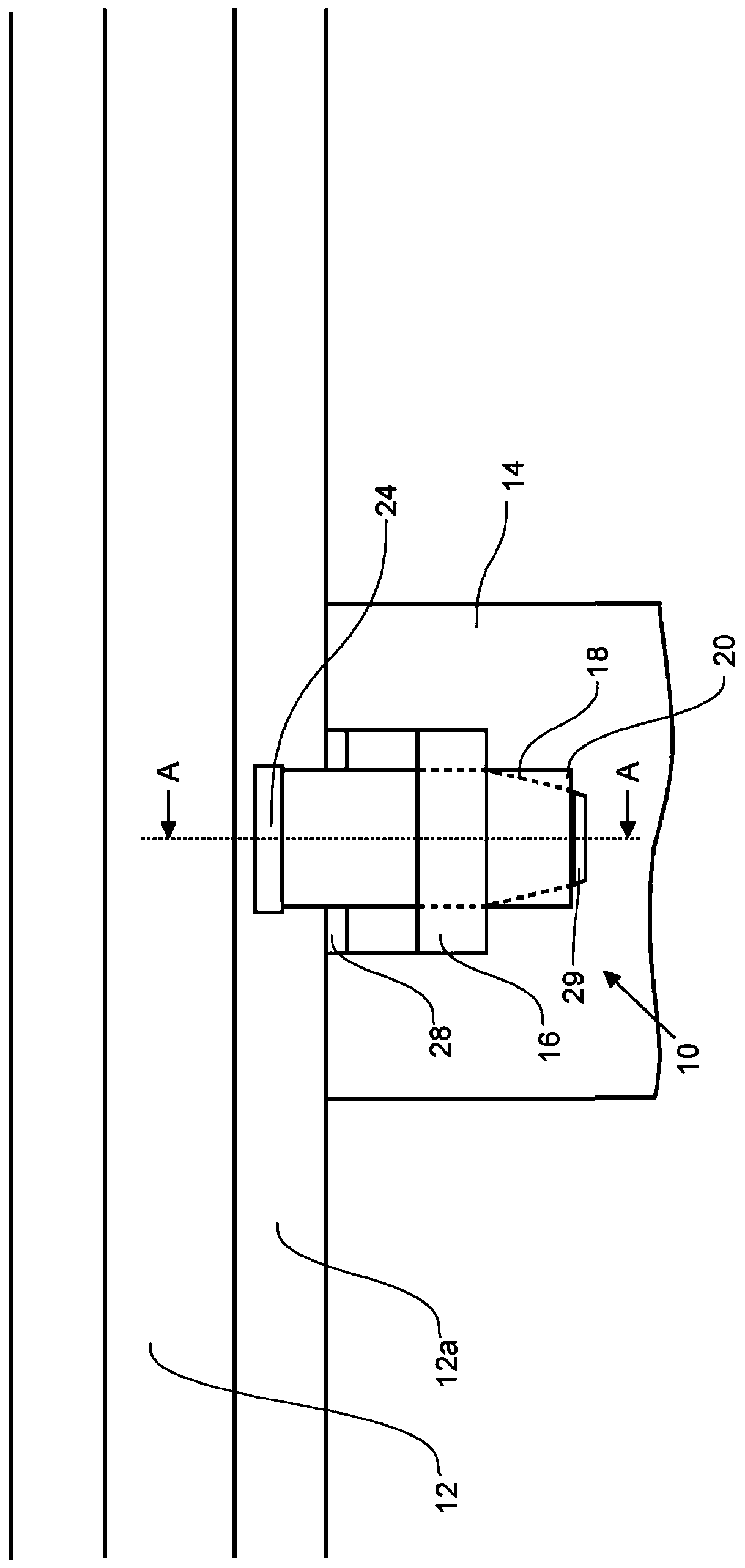
[0024] Figure 1a and 1b is a schematic top view of a preferred embodiment of a rail mounting device 10 according to the present invention. For clarity, those parts that would otherwise be covered in the top view are in the Figure 1a and 1b Shown in dotted line.

[0025] The rail mounting device 10 is used to secure a railroad rail 12 directly or indirectly to a reinforced concrete sleeper. In this description, indirect fixation is understood to mean that a spacer such as an electrically insulating plate is positioned between the guide rail 12 and the reinforced concrete sleeper 14 such that the guide rail 12 and the reinforced concrete sleeper 14 do not come into direct contact with each other. Direct fixation is understood to be the case when there is direct contact between the guide rail 12 and the reinforced concrete sleeper 14 . The device 10 has a first state when the guide rail 12 is not fixed, and has a second state when the guide rail is fixed, and the first and s...


PUM


Abstract

The object of the invention relates to a rail mounting device (10) for fixing railway rails (12) to reinforced concrete sleepers (14) which device (10) has a first rail (12) non-fixing state and a second rail (12) fixing state, and which device (10) contains an anchoring element (18) fixed to the reinforced concrete sleeper (14) provided with an open or closed bracket piece (16), and a rail-clamping plate (20) partially or entirely encompassed by the bracket piece (16) of the anchoring element (18), the essence of which is that the rail-clamping plate (20) is a flexible flat plate, and in thefirst state of the rail mounting device (10), the rail-clamping plate (20) is established at an angle to the upper plane (22) of the reinforced concrete sleeper (14) in such a way that the distance between the first end of the rail-clamping plate (20) closer to the rail (12) and the upper plane (22) of the reinforced concrete sleeper (14) is smaller than the distance between the second end of therail-clamping plate (20) more distant from the rail (12) and the upper plane (22) of the reinforced concrete sleeper (14), and in the second state of the rail mounting device (10), the rail-clamping plate (20) is fixed to the anchoring element (18) so that its first end is laid on the base (12a) of the rail (12) and the shape of the rail-clamping plate (20) is a convex curve viewed from the direction of the upper plane (22) of the reinforced concrete sleeper (14). The object of the invention also relates to a method for fixing railway rails (12) to reinforced concrete sleepers (14).

Description

technical field [0001] The object of the invention relates to a guide rail installation device for fixing railway guide rails to reinforced concrete sleepers, in particular for fixing without a base plate, said device having a non-fixed first state and a fixed guide rail second Two states, and the device comprises an anchoring element fixed to a reinforced concrete sleeper provided with an open or closed support piece, and a rail clamping plate partially or completely surrounded by the support piece of the anchoring element. [0002] The object of the invention also relates to a method for fixing guide rails laid on reinforced concrete sleepers. Background technique [0003] The task of a rail mounting device is to provide a strong and flexible connection between a railway rail and the sleepers that support it. Many rail mounting devices have been used over the course of railway history and can be divided into three broad categories based on the clamping method. [0004] T...

Claims


Application Information

Patent Timeline
Patent Type & Authority Applications(China)
IPC IPC(8): E01B9/28E01B9/30E01B9/60E01B13/02
CPCE01B9/306E01B29/24E01B9/38E01B9/486E01B9/02E01B9/52E01B9/48E01B9/60E01B2201/02
Inventor A.拉茨
Owner HR SYST HUNGARY ZRT
Why Eureka
Try Eureka