Assembling type overlapped cavity floor cover

A cavity floor and prefabricated technology, applied in the direction of floors, building components, buildings, etc., can solve problems such as heavy weight, affecting construction speed, and slow project progress

Active Publication Date: 2017-02-08
王海崴 +2
View PDF13 Cites 56 Cited by
  • Summary
  • Abstract
  • Description
  • Claims
  • Application Information

AI Technical Summary

Problems solved by technology

[0007] The purpose of the present invention is to promote the progress of building science and technology, organically combine the industrially produced prefabricated assembly-type cavity plate components without upper flanges with the reinforced concrete beams and columns poured on site to form an assembly-type laminated cavity floor, which adopts horizontal Superposition can also save the benefits generated by the floor space occupied by the exposed beams, and optimize the existing frame structure technical system; make full use of the advantages of industrialization of the factory, prefabricate and produce assembly-type upper-flange cavity plate components, and solve the weight of the components , Poor structural integrity, difficult implementation controllability, environmental pollution caused by on-site construction, heavy quality, high construction cost, slow progress of the project, a large number of building formwork and steel supports, resulting in long mold making time and affecting the construction speed, etc.

Method used


Image

  • Assembling type overlapped cavity floor cover
  • Assembling type overlapped cavity floor cover
  • Assembling type overlapped cavity floor cover

Examples


Embodiment Construction

[0019] The present invention will be further described below in conjunction with the accompanying drawings.

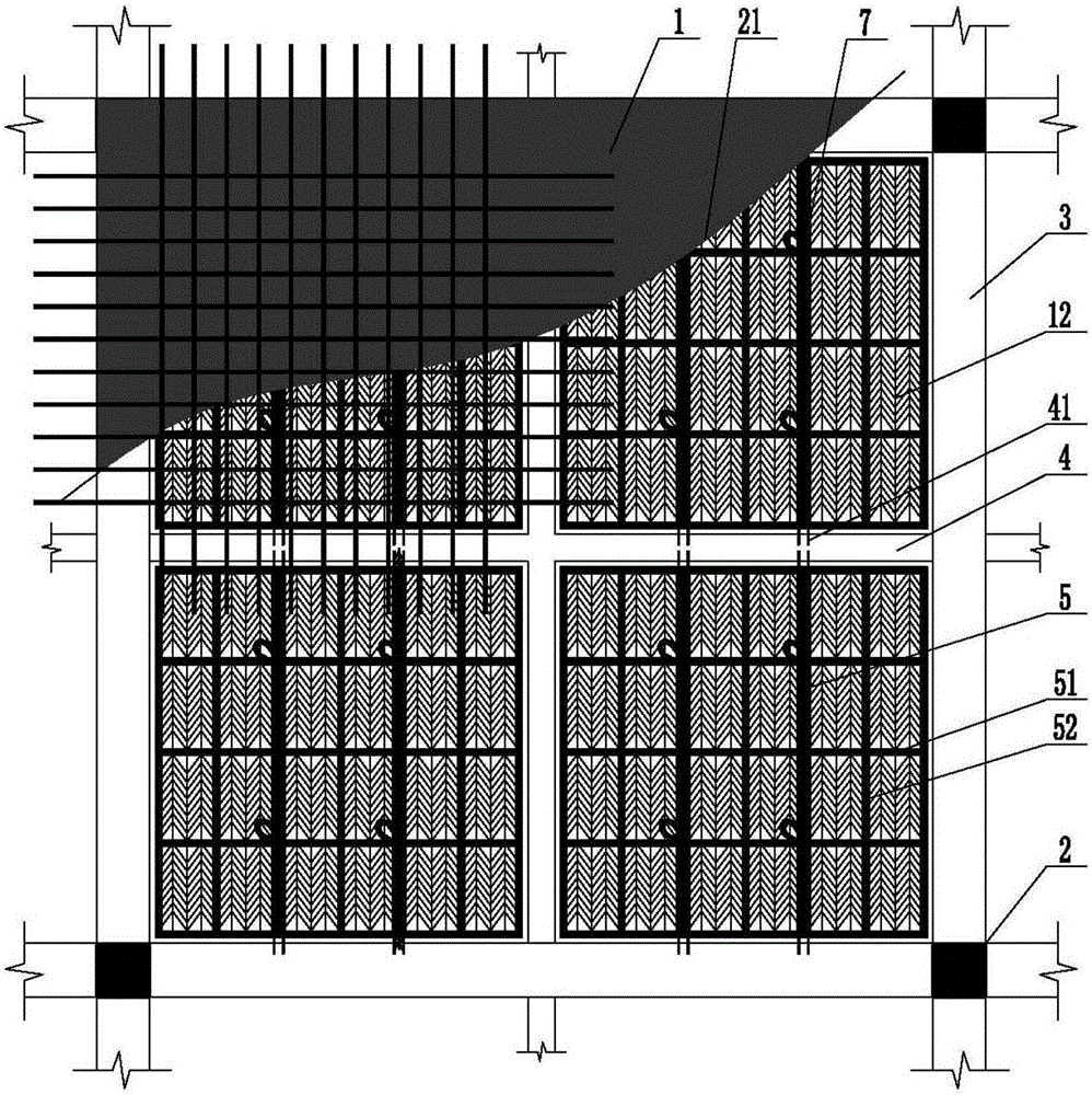
[0020] figure 1 This is a plan view of a prefabricated laminated cavity floor slab of the present invention. When the present invention is implemented, the prefabricated assembly line without upper flange cavity plate member 7 produced in the factory assembly line is transported to the construction site; the so-called columns and beams are steel bars Concrete structure or section steel structure; the fabricated upper flangeless cavity plate member and beam are divided into vertical stacking or horizontal stacking; the vertical stacking is to stack the fabricated upper flangeless cavity plate member on The top surface of the beam; the horizontal stacking is to stack the assembled non-top flange cavity plate member on the horizontal plane of the beam. When the column 2 and the beam 3 are shaped steel structures, the exposed ribbed steel bars 41 are directly welded to the sh...


PUM


Abstract

The invention provides an assembling type overlapped cavity floor cover. The assembling type overlapped cavity floor cover comprises columns, a main beam, an auxiliary beam, upper-flange-free cavity plate components and cast-in-situ reinforced concrete floor cover upper flange plates. The assembling type overlapped cavity floor cover is characterized in that the auxiliary beam is arranged in a column net formed by the columns and the main beam; the upper-flange-free cavity plate components are arranged on a framework of the auxiliary beam; the assembling type upper-flange-free cavity plate components and the beams are arranged in a vertical or horizontal overlapping manner, the vertical overlapping manner is to overlap the assembling type upper-flange-free cavity plate components to the top surfaces of the beams, and the horizontal overlapping manner is to overlap the assembling type upper-flange-free cavity plate components to the horizontal surfaces of the beams; and reinforced concrete is poured on the upper surfaces of the upper-flange-free cavity plate components to form assembling type cavity floor cover upper flange plates through overlapping, so as to form the assembling type overlapped cavity floor cover.

Description

Technical field [0001] The invention relates to a fabricated building system technology, in particular to a fabricated laminated cavity floor technology. Background technique [0002] In the 1980s, the production of precast concrete components in China was in a major development stage. In the process of housing construction in the country, the floor adopts hollow precast slab structure, large slab structure, cast-in-place concrete structure, cast-in-place concrete hollow floor structure, and cast-in-place concrete frame structure. , Cast-in-place concrete frame shear wall structure, etc., with the housing industrialization process, a few days ago, the steel-concrete composite structure and the steel-concrete composite cavity floor structure system have been rapidly developed. China's prefabricated floor has just started, adopting Longitudinal laminated board, that is, the assembled solid large board is laminated on the beam. [0003] For example, ZL200410082381.9 "a kind of fastin...

Claims


Application Information

Patent Timeline
Patent Type & Authority Applications(China)
IPC IPC(8): E04B5/28E04B5/32
CPCE04B5/28E04B5/326
Inventor 王海崴王本淼李国强贾英杰刘青杨建军马锋
Owner 王海崴
Why Eureka
Try Eureka