[0022] The principles and features of the present invention will be described below with reference to the accompanying drawings. The examples cited are only used to explain the present invention, and are not used to limit the scope of the present invention.
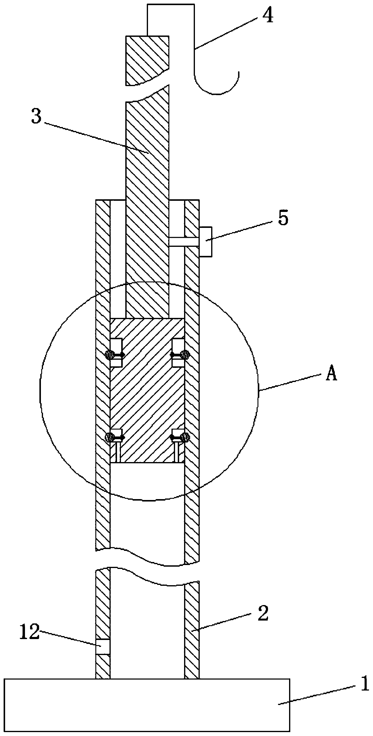
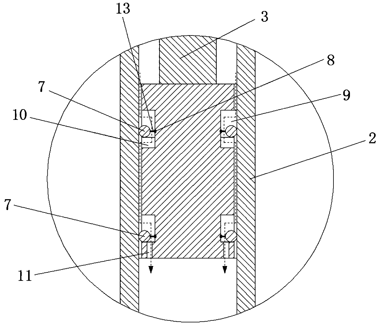
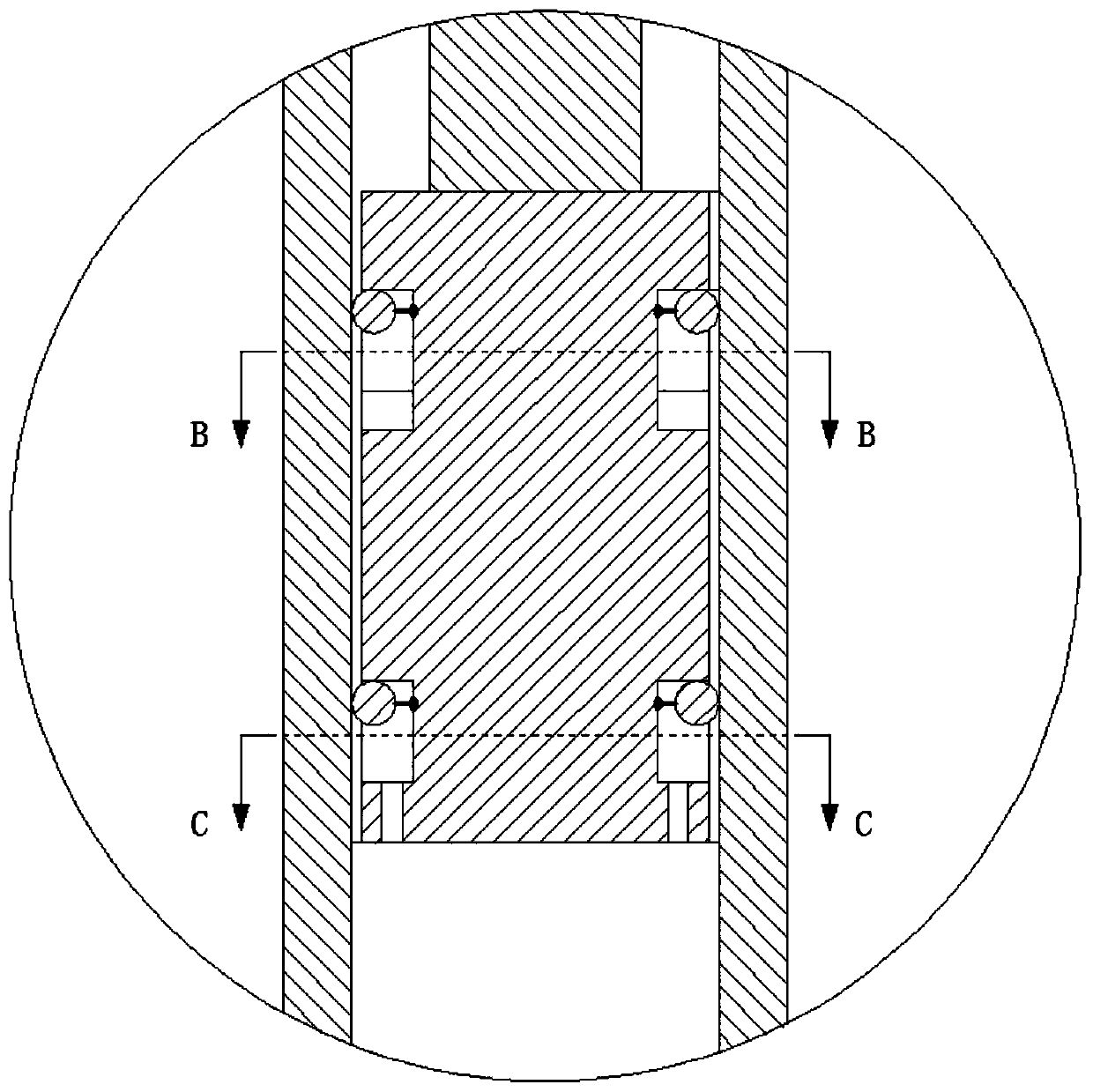
[0023] Such as figure 1 As shown, an infusion stand includes a base 1, a fixed tube 2 and a lifting rod 3, and the fixed tube 2 is vertically fixed on the base 1. The lifting rod 3 is slidable up and down in the fixed tube 2, and the top of the lifting rod 3 extends out of the fixed tube 2 and is provided with a hook 4 for hanging the medicine bottle. A screw 5 is provided on the top of the side wall of the fixed pipe 2, and the screw 5 threaded through the side wall of the fixed pipe 2 and then abuts the corresponding position of the lifting rod 3 so that the lifting rod 3 is opposed to the The position of the fixed pipe 2 is fixed. The infusion stand also includes a sliding seat 6, two sealing rings 7 and two positioning rings 8. The sliding seat 6 is a cylindrical structure, which is fixed on the lower end of the lifting rod 3 and is slidable up and down in the fixed tube 2. Two rings of sliding grooves 9 are provided on the outer side wall of the sliding seat 6. The lower part of the upper sliding groove 9 is provided with a groove 10, and the lower part of the lower sliding groove 9 is provided with a straight hole 11. Such as Figure 4 with 5 As shown, both the groove 10 and the straight hole 11 are provided with multiple, which are uniformly annularly arranged at the lower part of the corresponding sliding groove 9. A buffer hole 12 is provided on the side wall of the fixed pipe 2 near the bottom.
[0024] The two sealing rings 7 are respectively sleeved on the outer periphery of the sliding groove 9 slidably up and down. Such as figure 2 As shown, when the lifting rod 3 is received in the fixed tube 2 downward, the sealing ring 7 slides upwards on the upper part of the corresponding sliding groove 9 and seals the sliding seat 6 and the fixed tube 2 The gap between the inner walls allows the air inside the fixed pipe 2 to be discharged from the buffer hole 12 at a constant speed and restricts the lifting rod 3 from being able to be received into the fixed pipe 2 at a constant speed, thereby avoiding hanging on the hook The medicine bottle on 4 was shaken and dropped or shattered directly. Such as image 3 As shown, when the lifting rod 3 extends upward to the outside of the fixed pipe 2, the sealing ring 7 slides down to the lower part of the corresponding chute 9 and causes the outside air to follow the lifting rod 3 The gap with the fixed pipe 2 first passes through the sealing ring 7 at the top, then passes through the groove 10 and the sealing ring 7 at the bottom, and finally goes down from the straight hole 11 It enters into the inside of the fixed pipe 2 to keep the air pressure inside the fixed pipe 2 in a balanced state so as to easily extend the lifting rod 3 out of the fixed pipe 2.
[0025] The working principle of the present invention will be described below when the lifting rod 3 is received in the fixed pipe 2 downward or extends upward to the outside of the fixed pipe 2:
[0026] When the lifting rod 3 is received in the fixed pipe 2 downward
[0027] Such as figure 2 As shown, because the outer diameter of the sealing ring 7 is slightly larger than the inner diameter of the fixed pipe 2, the outer diameter of the sliding seat 6 is smaller than the inner diameter of the fixed pipe 2. When the lifting rod 3 falls, it will rely on the friction between the sealing ring 7 and the inner wall of the fixed pipe 2. The sealing ring 7 is driven to slide upward in the sliding groove 9 and reach the upper part of the sliding groove 9. As the lifting rod 3 descends, the sealing ring 7 will maintain its position in the upper part of the sliding groove 9. When the sealing ring 7 is at the upper part of the sliding groove 9, it seals the gap between the sliding seat 6 and the inner wall of the fixed pipe 2, so that the air inside the fixed pipe 2 cannot pass through the outer circumference of the sliding seat 6 during the descending process of the lifting rod 3 When the air is discharged upward, the air inside the fixed pipe 2 can only be compressed and discharged from the buffer hole 12 on the side wall at the bottom of the fixed pipe 2. When it is discharged from the buffer hole 12, it will form an upward reaction force on the lifting rod 3, and then The lifting rod 3 can be lowered at a constant speed, and when the sliding seat 6 is lowered to the lower position of the buffer hole 12, the air in the fixed pipe 2 corresponding to the lower part of the sliding seat 6 cannot be discharged from the buffer hole 12, forming a certain air pressure Resistance, the air pressure resistance can greatly slow down the descending speed of the lifting rod 3, so as to ensure that the suspended medicine bottle on the top of the lifting rod 3 will not be affected by the shock impact, and prevent the medicine bottle from being shaken and dropped or directly shattered.
[0028] When the lifting rod 3 extends upward to the outside of the fixed pipe 2
[0029] Such as image 3 As shown, when the lifting rod 3 is stretched relative to the fixed pipe 2, the lifting rod 3 will slide upwards and will drive the sealing ring 7 to slide down in the slide groove 9 and reach the lower part of the slide groove 9, as the lifting rod 3 rises, the sealing ring 7 The position will remain unchanged at the bottom of the chute 9. Due to the design of the groove 10 and the straight hole 11, when the sealing ring 7 is in the lower part of the sliding groove 9, it cannot seal the gap between the sliding seat 6 and the inner wall of the fixed pipe 2, and the outside air will pass through the top of the sliding seat 6 and The gap between the inner walls of the support tube 3 passes through the upper seal ring 7 toward the inner side of the sliding seat 6, and then passes through the gap between the middle of the slide seat 6 and the inner wall of the support tube 3, and then passes through the inner side of the slide seat 6. Pass the lower sealing ring 7, and finally enter the fixed pipe 2 down from the straight hole 11 ( image 3 The direction of the arrow), so that the air pressure inside the fixed pipe 2 is in a balanced state, and it is easier to stretch the lifting rod 3 without any resistance.
[0030] When the lifting rod 3 is received in the fixed pipe 2 downwards, the sealing ring 7 needs to maintain sufficient sealing to buffer the descending lifting rod 3, otherwise, when the lifting rod 3 is received downwards into the fixed pipe 2, it is fixed The air inside the tube 2 can blow up through the sealing ring 7, and the lifting rod 3 cannot compress the air in the fixed tube 2, and the air in the fixed tube 2 cannot form a reaction force on the lifting rod 3, resulting in the falling lifting rod 3 There will still be a big impact, which will shake the medicine bottle off or directly shatter it. As the sealing ring 3 falls on the lifting rod 3, it relies on the friction force between the sealing ring 7 and the inner wall of the fixed pipe 2 to slide up and reach the upper part of the chute 9 to achieve sealing, such as Figure 7 As shown, if the friction force received at different positions of the sealing ring 3 is inconsistent, its axial direction relative to the sliding seat 6 will be deflected, and finally the outer circumference of the sealing ring 3 and the inner wall of the fixed pipe 2 will form a gap and deflate. The present invention solves the above-mentioned technical problem of deflection and air leakage of the sealing ring 3 through the subordinate solutions:
[0031] The two positioning rings 8 are arranged in a one-to-one correspondence with the two sealing rings 7, and they are respectively sleeved on the two sliding grooves 9 and corresponding to the positions inside the sealing rings 7. The positioning ring 8 is connected to the corresponding sealing ring 7 through a plurality of connecting bars 13 and slides up and down synchronously with the sealing ring 7, as follows: Image 6 As shown, one end of the connecting strip 13 is uniformly annularly connected to different positions of the positioning ring 8, and the other end thereof radiates toward the sealing ring 7 and connects to corresponding positions on the inner wall of the sealing ring 7. The positioning ring 8 sticks to the bottom of the corresponding sliding groove 9 to prevent the sealing ring 7 from deflecting relative to the axial direction of the sliding seat 6 during the up and down sliding process, which affects the sealing effect. The positioning ring 8 is connected to the sealing ring 7 through a rigid connecting strip 13, so that the sealing ring 7 and the positioning ring 8 are always in the same plane. Because the positioning ring 8 can stick to the corresponding sliding groove 9 during the upward sliding of the sealing ring 7 The bottom of the groove, that is, the side wall of the sliding seat 6 slides upwards synchronously. Under the action of the side wall of the sliding seat 6, the positioning ring 8 can only slide up and down without being able to deflect horizontally with respect to the axial direction of the sliding seat 6, thereby realizing that the sealing ring 7 cannot Relative to the axial horizontal deflection of the sliding seat 6, the two are always on the same horizontal plane, and the sealing ring 7 will not deflate.
[0032] The above descriptions are only preferred embodiments of the present invention and are not intended to limit the present invention. Any modification, equivalent replacement, improvement, etc. made within the spirit and principle of the present invention shall be included in the protection of the present invention. Within range.