Reinforced tire bead structure with edge coated with nylon wrapping cloth and preparation method thereof

A nylon-wrapped and reinforced technology, which is applied in the direction of tires, tire edges, tire parts, etc., can solve problems such as cracks in the bead, separation of steel wires and rubber, deformation, etc., to reduce failure rates, reduce stress concentration, good transition effect

Pending Publication Date: 2019-08-27
GITI RADIAL TIRE (ANHUI) CO LTD
0 Cites 2 Cited by

AI-Extracted Technical Summary

Problems solved by technology

[0002] Domestic commercial trucks generally have the phenomenon of overloading and driving for a long time. During the use of tires, cracks and deformations often occur in the bead parts, which become frequent parts of tire failures, affecting the life and performance of tires. There are many, such as carcass, steel wir...

Method used

Further, the nylon cloth 8 is 3mm to 9mm in the inner side of the steel wire cloth 7, that is, the lower end point near the carcass cord 1 side and the turn-up end point of the carcass cord 1 is 3mm to 9mm. The transition between the end point of the turn-up cloth 7 and the steel wire cloth 7 through the nylon cloth 8 can effectively reduce the stress concentration phenomenon of the end point of the turn-up of the carcass cord 1. , because the lower end point of the inner side of the nylon cloth 8 also has a small stress, and being too close to the turned-up end point of the carcass cord 1 cannot reduce the stress concentration. Due to fluctuations in factory manufacturing, it may even lead to The point coincides with the turn-up end point of the carcass cord 1, which intensifies the stress concentration phenomenon of the turn-up end point of the carcass cord 1. If the difference between the inner lower end point of the nylon cloth 8 and the turn-up end point of the carcass cord 7 is too large, the inner lower end point of the nylon cloth 8 will be close to the contact position between the rim and the tire with higher stress, and the tension of the inner lower end point of the nylon cloth 8 will be aggravated. Stress concentration phenomenon, and will lead to material waste, increase tire cost.
Further, the thickness of described nylon wrapping 8 is 0.8mm to 1.6mm, and described nylon wrapping 8 and steel wire wrapping 7 fitting surfaces are arranged along its respective internal cord crossing, and described nylon wrapping 8 The cord density is 50 to 130 cords/dm, and the width is 2...

Abstract

The invention discloses a reinforced tire bead structure with an edge coated with nylon wrapping cloth and a preparation method thereof. The nylon wrapping cloth is arranged as a single layer and wraps around the end point of the outer side of a steel wire wrapping cloth, and the cross section is in an inverted U shape. The end point of the inner side of the nylon wrapping cloth is disposed between the reservedly wrapped end point of the outer side of a tire body cord fabric and the reservedly wrapped end point of the outer side of the steel wire wrapping cloth; and the nylon wrapping cloth has an angle of reducing stress concentration, and the height of the reservedly wrapped end point of the outer side of the steel wire wrapping cloth is larger than the height of the reservedly wrapped end point of the outer side of the tire body cord fabric. A layer of nylon wrapping cloth is used for edge covering at the end point of the outer side of the steel wire wrapping cloth and extends between the reservedly wrapped end point of the tire body cord fabric and the steel wire wrapping cloth, and the stress concentration of a tire bead part is reduced. An angled nylon wrapping cloth is additionally arranged between the outer end point of the steel wire wrapping cloth and rubber and between the reservedly wrapped end point of a carcass and the steel wire wrapping cloth to reduce stress concentration. The rigidity of the nylon wrapping cloth is higher than that of the rubber, the rigidity of the tire bead part can be improved, and the failure rate of the tire bead part of the tire is reduced.

Application Domain

TyresTyre beads

Technology Topic

Image

  • Reinforced tire bead structure with edge coated with nylon wrapping cloth and preparation method thereof
  • Reinforced tire bead structure with edge coated with nylon wrapping cloth and preparation method thereof
  • Reinforced tire bead structure with edge coated with nylon wrapping cloth and preparation method thereof

Examples

  • Experimental program(1)

Example Embodiment

[0036] The present invention will be further explained below in conjunction with the drawings:
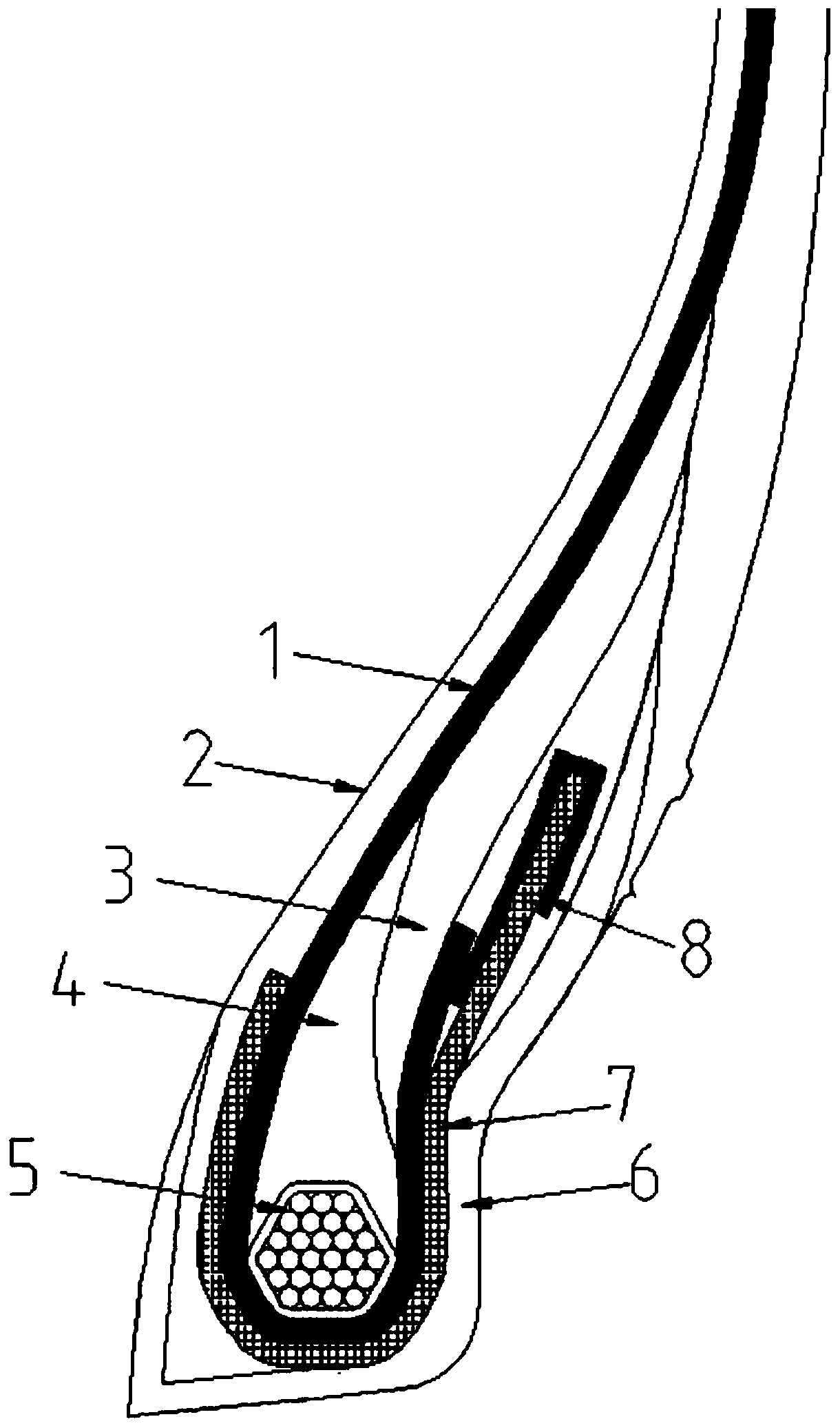
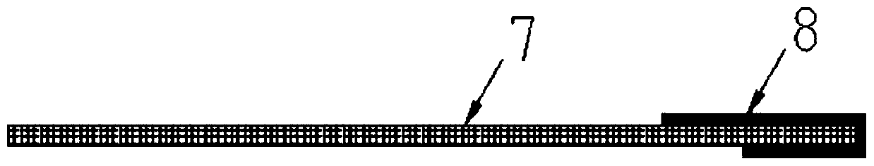
[0037] Such as figure 1 The shown reinforced bead structure with nylon cloth edging includes an inner liner 2, a carcass cord 1, a steel wire cloth composite, and a wear-resistant rubber 6 wrapped on the outside of the bead. , The sidewall rubber and the traveller 5, the hard apex 4 and the soft apex 3 wrapped by the carcass cord 1 and the steel wire cloth 7, the steel wire cloth composite part includes the steel wire cloth 7 and the nylon cloth 8, so The nylon covering cloth 8 is arranged as a single layer and covered at the outer end of the steel wire covering 7 and has an inverted U-shaped cross section. The inner end of the nylon covering 8 is set at the outer turn-up end of the carcass cord 1 and the wire covering 7 between the outer turn-up end points, and the nylon wrap 8 is provided with an angle for reducing stress concentration, and the outer turn-up end point of the steel wire wrap 7 is higher than the outer turn-up end point of the carcass cord 1.
[0038] Further, the thickness of the nylon covering cloth 8 is 0.8mm to 1.6mm, and the bonding surfaces of the nylon covering cloth 8 and the steel wire covering cloth 7 are arranged crosswise along their respective inner cords. The cords of the nylon covering cloth 8 The density is 50 to 130 pieces/dm, the width is 25mm to 65mm, the angle between the cord of the nylon covering 8 and the tire circumferential direction is set to 25° to 65°, and the direction of the nylon covering 8 and the steel wire covering 7 can be crossed. Effectively reduce the stress concentration phenomenon at the outer end of the steel wire cloth. If the angle of the nylon cloth 7 is too small, the angle between the steel wire and the steel wire cloth 7 is too small, which cannot reduce the stress concentration at the outer end of the steel wire cloth 7. If the angle of the nylon cloth 8 is too large, it will The angle between the carcasses with an angle of 90 degrees is too small to reduce the stress concentration at the turn-up end of the carcass. The density of nylon covering 8 is too small to reduce stress concentration. Too large a density will make the distance between nylon cords too small, and the nylon cords will be easily separated from the rubber, resulting in failure of the bead and waste of materials. Increase tire costs.
[0039] Further, the difference between the lower end of the nylon covering 8 on the inner side of the steel wire covering 7 that is close to the side of the carcass ply 1 and the turn-up end of the carcass cord 1 is 3mm to 9mm, at the turn-up end of the carcass ply 1 The transition with the steel wire cloth 7 through the nylon cloth 8 can effectively reduce the stress concentration of the carcass cord 1 turn-up end point. If the inner lower end of the nylon cloth 8 and the carcass cord 1 turn-up end point are too small, the nylon The lower end of the inner side of the covering cloth 8 also has a small stress, too close to the turn-up end of the carcass cord 1 can not reduce the stress concentration. Due to the fluctuation of the factory manufacturing, it may even cause the inner lower end of the nylon covering 8 to contact the tire. The end points of the turn-up of the body cord 1 overlap, which aggravates the stress concentration phenomenon of the turn-up end of the carcass cord 1. If the difference between the inner lower end of the nylon covering 8 and the turn-up end of the carcass cord 7 is too large, the inner lower end of the nylon covering 8 will be close to the contact part of the rim and the tire with higher stress, which intensifies the inner lower end of the nylon covering 8 Stress concentration will cause material waste and increase tire cost.
[0040] Further, the difference between the lower end of the nylon cloth 8 on the outside of the steel wire cloth 7 and the outer end of the steel wire 7 is 10mm to 30mm, if the difference between the lower end of the nylon cloth 8 and the outer end of the steel wire 7 Too small, the lower end of the outer side of the nylon cloth 8 also has a small stress, too close to the outer end of the steel wire cloth 7 can not reduce the stress concentration, due to factory manufacturing fluctuations, even the lower end of the outer side of the nylon cloth 8 The point coincides with the outer end point of the steel wire cloth 7, which intensifies the stress concentration phenomenon at the outer end of the steel wire cloth 7. At the same time, the nylon cloth 8 also has a certain degree of rigidity. The width of the nylon cloth 8 on the outside of the steel wire cloth 7 is too narrow. During the manufacturing process, the outer nylon cloth 8 of the steel wire cloth 7 and the steel wire cloth 7 may become separated. Problems increase the difficulty of factory manufacturing. If the difference between the lower end of the outer side of the nylon cloth 8 and the end of the steel wire cloth 7 is too large, it will approach the contact part between the rim and the tire with higher stress, which will aggravate the stress concentration at the lower end of the outer side of the nylon cloth 8 and cause material waste. Increase tire costs.
[0041] Further, the difference between the outer end of the steel wire covering 7 and the turn-up end of the carcass cord 1 is 10 mm to 20 mm, and the stress at the outer end of the steel wire covering 7 and the turn-up end of the carcass cord 1 is higher. If the spread is too small, it will aggravate the stress concentration and cause the bead to malfunction. If the spread between the two ends is too large, the outer end of the steel wire cloth 7 will be too high or the carcass turn-up end will be too low. If the outer end of the steel wire cloth 7 is too high, it will be close to the sidewall position where the tire is deformed when the tire is running. Excessive deformation between the steel wire and the rubber at the outer end of the steel wire cloth 7 will cause the steel wire to separate from the rubber and cause failure. If the turn-up end of the carcass cord 1 is too low, it will be close to the contact part of the rim and the tire with higher stress, which intensifies the stress concentration at the turn-up end of the carcass cord 1.
[0042] Further, the thickness of the steel wire cloth 7 is 1.6 mm to 2.6 mm, the width is 60 mm to 120 mm, and the angle between the steel wires of the steel wire cloth 7 and the tire circumferential direction is 20°-50°. The carcass and the tire are at 90 degrees in the circumferential direction and the end points are flush. The rigidity is too strong. The steel wire cloth 7 has a certain angle to reduce its own rigidity, so that the bead part gradually transitions from hard to soft, effectively reducing the stress concentration in the bead part phenomenon.
[0043] The carcass cord 1, the steel wire covering 7, the hard apex 4, and the sidewall wear-resistant rubber have strong rigidity. The inner end of the steel wire covering 7, the turn-up end of the carcass cord 1, the upper end of the hard apex 4, the tire The outer end points of the side wrapping fabric and the outer end points of the wear-resistant rubber 6 are arranged in the bead position from low to high according to the above-mentioned difference, which can make the tire gradually transition from the rigid bead part to the weaker sidewall part , Effectively prevent the stress concentration phenomenon at the above-mentioned endpoints in the bead area.
[0044] The finite element analysis in the table below further illustrates the technical effects of this case;
[0045]
[0046] By comparing the finite element analysis results of the two analysis conditions of the steel wire covering 7 with nylon covering 8 at the outer end point and the unbound nylon covering 8 scheme, the strain of the unbound nylon covering 8 scheme The sum strain energy is an index of 100. It can be seen that the strain and strain energy of the turn-up end of the carcass and the outer end of the chafer in the 8 plan with edging nylon are smaller than those of the 8 plan without edging.
[0047] by Figure 3-Figure 6 The finite element analysis strain diagram and Figure 7-10 The finite element analysis of the strain energy diagram of the bead part shows that the stress and strain energy concentration area of ​​the bead position with the nylon covering 8 plan is significantly smaller than the non-nylon covering 8 plan, which effectively reduces the stress concentration at the bead part.
[0048] Below for Figure 3-Figure 10 Give further explanation;
[0049] by comparison image 3 with Figure 4 , It can be seen that the finite element analysis carried out under the conditions of 100% air pressure and 100% load shows that the area of ​​the strain and high strain area of ​​the carcass turn-up end point and the outer end point of the steel wire cover 7 with nylon covering 8 scheme is significantly smaller than that of no nylon covering Fabric 8 scheme (the darker the color in the picture, the greater the strain).
[0050] by comparison Figure 5 with Image 6 It can be seen that the finite element analysis carried out under the conditions of 130% air pressure and 150% load shows that the strain and high-strain area of ​​the carcass turn-up end point and the outer end point of the steel wire cover 7 with the nylon covering 8 scheme are significantly smaller than those without the nylon covering Fabric 8 scheme (the darker the color in the picture, the greater the strain).
[0051] by comparison Figure 7 with Figure 8 , It can be seen that the finite element analysis carried out under the conditions of 100% air pressure and 100% load shows that the area of ​​the strain energy and high strain energy area of ​​the carcass turn-up end point and the outer end point of the steel wire cover 7 with the nylon covering 8 scheme is significantly smaller than that of none Nylon covering 8 plan (the darker the color in the picture indicates the greater the strain energy).
[0052] by comparison Picture 9 with Picture 10 , It can be seen that the finite element analysis carried out under the conditions of 130% air pressure and 150% load shows that the area of ​​the strain energy and high strain energy area of ​​the carcass turn-up end point and the outer end point of the steel wire cover 7 with the nylon covering 8 scheme is significantly smaller than that of none Nylon covering 8 plan (the darker the color in the picture indicates the greater the strain energy).
[0053] At the same time, it is worth mentioning that this kind of reinforced bead needs to be prepared by a special processing method, including the following preparation steps:
[0054] 1: Prefabricated nylon covering cloth 8, the cord of nylon covering cloth 8 is selected from nylon 66 420D/1 or nylon 66 840D/2 or nylon 66 1260D/2, and the thickness is 0.8-1.6mm and the density is 50 by the calender. Up to 130 pieces of nylon covering cloth 8;
[0055] 2: The oblique cutting machine cuts the steel wire cloth 7 obliquely from 20° to 50°, and the nylon cloth 8 obliquely cuts from 25° to 65°;
[0056] 3: The steel wire covering cloth 7 and the nylon covering cloth 8 are pasted in a cross pattern and combined by an applicator to form a whole for hemming;
[0057] 4: When the embryo is formed, the inner lining layer 2 is cross-fitted with the steel wire cloth composite part, and the side of the nylon cloth 8 faces outward;
[0058] 5: Fit the carcass cord 1 symmetrically, and transfer the matching traveler 5, hard apex 4 and soft apex 3 to the forming drum by a mechanical device, and perform the remaining forming steps;
[0059] 6: After molding, vulcanize the tire, inspect and package.
[0060] The cords of the nylon cloth covered are nylon 66 420D/1 or nylon 66 840D/2 or nylon 66 1260D/2.
[0061] The above-mentioned embodiments only describe the preferred embodiments of the present invention, and do not limit the scope of the present invention. Without departing from the design spirit of the present invention, those of ordinary skill in the art have made various contributions to the technical solutions of the present invention. Variations and improvements should fall within the protection scope determined by the claims of the present invention.

PUM

PropertyMeasurementUnit
Thickness0.8 ~ 1.6mm
Width25.0 ~ 65.0mm
Thickness1.6 ~ 2.6mm
tensileMPa
Particle sizePa
strength10

Description & Claims & Application Information

We can also present the details of the Description, Claims and Application information to help users get a comprehensive understanding of the technical details of the patent, such as background art, summary of invention, brief description of drawings, description of embodiments, and other original content. On the other hand, users can also determine the specific scope of protection of the technology through the list of claims; as well as understand the changes in the life cycle of the technology with the presentation of the patent timeline. Login to view more.

Similar technology patents

Classification and recommendation of technical efficacy words

  • Good transition
  • Reduce stress concentration

Method, device and equipment for adjusting ink discharge amount to compensate for abnormal nozzle, and medium

ActiveCN110202933AIncrease the probability of compensationGood transitionPrintingSpray nozzleEngineering
Owner:SENDA SHENZHEN TECH CO LTD

Adjustable Rear Rotor Discharge Flights

ActiveUS20090143123A1Optimize straw length and residue distributionGood transitionGrain huskingGrain polishingCombine harvester
Owner:DEERE & CO

High-voltage cable terminal shunt-type antitheft grounding and measuring device

ActiveCN107632185AReasonable designGood transitionTesting dielectric strengthIndicating presence of current/voltageShunt typesHinge angle
Owner:ELECTRIC POWER SCI & RES INST OF STATE GRID TIANJIN ELECTRIC POWER CO +2

Flexible heart valve

InactiveUS20050096739A1Reduce stress concentrationHeart valvesProsthesisCommissure
Owner:EDWARDS LIFESCIENCES CORP

Excavating method for jump-digging of double-side wall guide pit combined arch part of tunnel

ActiveCN102182466AReduce stress concentrationReduce surrounding rock disturbanceUnderground chambersTunnel liningSubsidenceStress concentration
Owner:CHINA RAILWAY SHANGHAI DESIGN INST GRP

Valve body and seal assembly

InactiveUS6955181B1Reduce stress concentrationReduce elastomer stressCheck valvesBuilding constructionsEngineeringStress concentration
Owner:S P M FLOW CONTROL
Why Eureka
Try Eureka