Driving control method and driving control device for loom

A loom, rotary drive technology, applied in looms, textiles, textiles and papermaking, etc., can solve problems such as weak beating force, no rise of the main shaft, and thick and thin sections, so as to prevent insufficient beating force and reduce load Effect

Active Publication Date: 2022-04-15
TSUDAKOMA KOGYO KK
View PDF12 Cites 0 Cited by
  • Summary
  • Abstract
  • Description
  • Claims
  • Application Information

AI Technical Summary

Problems solved by technology

In addition, when the number of heald frames used in the shedding device is large, or when a large force is required to drive the heald frames due to the type of warp used for weaving or the set tension, the shedding device is driven by a prime mover. In looms in which the motor is the drive source, a large load is applied to the main shaft drive unit at the start of the loom
Therefore, in this case, if an attempt is made to increase the spindle speed in a short period of time as described above, the loom will also be in a state where an excessive load is applied to the spindle drive device.
[0005] Moreover, when the loom is in a state where an excessive load is applied to the main shaft drive device when the loom is started as described above, depending on the state of the loom at this time, etc., there may be a problem that the rotational speed of the main shaft is below the assumed starting speed. The speed does not rise to the set speed within the time, and weaving cannot be carried out in the desired state, so that the loom becomes a state where defects such as thick and thin sections occur in the fabric
But, like this, under the state that the rotational speed of main shaft is low, the beating-up force that the swinging motion of reed produces is also weak, therefore, the weft yarn that is inserted weft is not fully beating-up in the meantime, and loom sometimes becomes to produce thin section. status

Method used


Image

  • Driving control method and driving control device for loom
  • Driving control method and driving control device for loom
  • Driving control method and driving control device for loom

Examples


Embodiment Construction

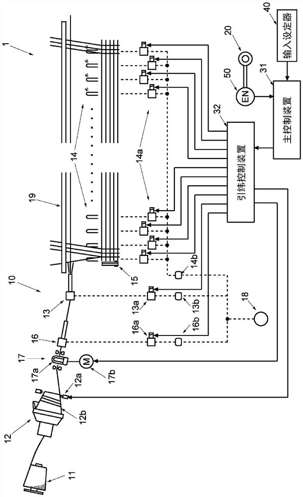
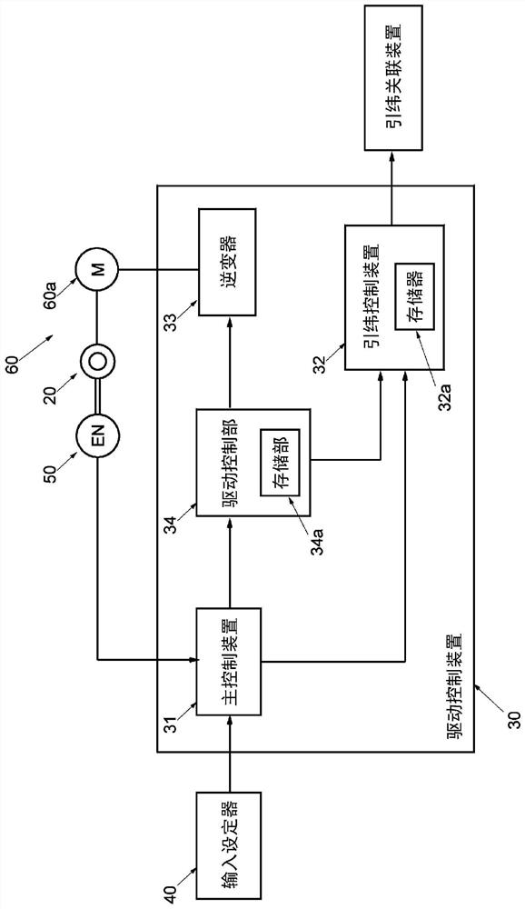
[0063] Below, based on Figure 1~3 An example of the present invention will be described. However, in this embodiment, the present invention will be described by taking an air jet loom as an example of a loom as a premise.

[0064] Such as figure 1 As shown, in the air jet loom 1, the weft insertion device 10 includes a yarn supply body 11, a length-measuring storage device 12 that only stores the weft yarn drawn from the yarn supply body 11 for a length corresponding to the weft insertion length, and is used for The main nozzle 13 for inserting the weft yarn, the plurality of sub-nozzles 14 for assisting the flight of the weft yarn injected from the main nozzle 13, and the yarn supply cutter 15 for cutting the inserted weft yarn. In addition, in the illustrated example, the weft insertion device 10 includes an auxiliary main nozzle 16 provided on the upstream side of the main nozzle 13 to assist the weft insertion of the main nozzle 13, and a weft yarn for applying a brakin...


PUM


Abstract

A drive control method and drive control device for a loom. In a loom, the prime mover motor in the spindle drive device that drives the spindle is controlled so that the spindle is rotated at a preset speed during steady state operation. drive. In the driving control method of the loom, the starting rotation speed is set in advance, the starting rotation speed is set to a rotation speed lower than the set rotation speed, and is set to be lower than the rotation speed determined in consideration of the load of the main shaft driving device and is set. 25% or more of the fixed speed, during the start-up of the loom from the start time until the main shaft speed reaches the set speed, start with weft insertion during the start-up period of the loom for more than one cycle, and follow the start-up speed from The control of the prime mover motor at the start time, and after the time when the rotation speed of the main shaft reaches the starting rotation speed, the rotation speed of the main shaft is increased from the starting rotation speed to the set rotation speed according to a predetermined rotation speed increase method Controls the drive of the prime mover.

Description

technical field [0001] The present invention relates to a driving control method for a loom and a driving control device thereof. In the loom, the principle of driving the main shaft is controlled in such a manner that the main shaft is driven at a predetermined rotational speed during steady state operation. Drive the motor. Background technique [0002] In the loom, for example, as disclosed in Patent Document 1, the rotational speed of the main shaft during steady-state operation is preset as a set rotational speed, and during steady-state operation, the main shaft is driven by a prime mover motor so that it The set rotation speed is driven to rotate, thereby performing weaving. Moreover, in general looms in recent years, when the loom is started from a stopped state, the loom is started such as by controlling the drive of the prime mover motor so that the rotation speed of the main shaft is within a short start time (e.g., equivalent to The above-mentioned set speed ca...

Claims


Application Information

Patent Timeline
Patent Type & Authority Patents(China)
IPC IPC(8): D03D51/00D03D47/27
CPCD03D51/005D03D47/275D03D51/002D03D51/12
Inventor 伊藤直幸小堀裕一朗
Owner TSUDAKOMA KOGYO KK
Why Eureka
Try Eureka