
Electric connector

An electrical connector, butt connector technology, applied in the direction of connection, two-part connection device, circuit, etc., can solve the problem that the welding effect of the welding part and the circuit board cannot be guaranteed, the auxiliary shielding cover cannot be movably installed, and the welding part cannot be observed first. position and other issues, to achieve the effect of reducing the interference of the line of sight, good sealing and shielding effect, and shortening the mutual influence

Active Publication Date: 2019-08-27
DEYI PRECISION ELECTRONIC IND CO LTD PANYU
View PDF4 Cites 0 Cited by
  • Summary
  • Abstract
  • Description
  • Claims
  • Application Information

AI Technical Summary

Problems solved by technology

[0007] However, if the rear end of the auxiliary shielding cover is directly welded to the circuit board to form a ground loop, this can shorten the grounding path of the current of the auxiliary shielding cover, but the auxiliary shielding cover cannot be movably installed on the rear end of the shielding shell. In other words, the first position for observing the soldering part cannot be formed, and the welding effect between the soldering part and the circuit board cannot be guaranteed, which in turn affects the signal transmission of the guaranteed terminal

Method used


Image

  • Electric connector
  • Electric connector
  • Electric connector

Examples


Embodiment Construction

[0093] In order to facilitate a better understanding of the purpose, structure, features, and effects of the present invention, the present invention will now be further described in conjunction with the accompanying drawings and specific embodiments.

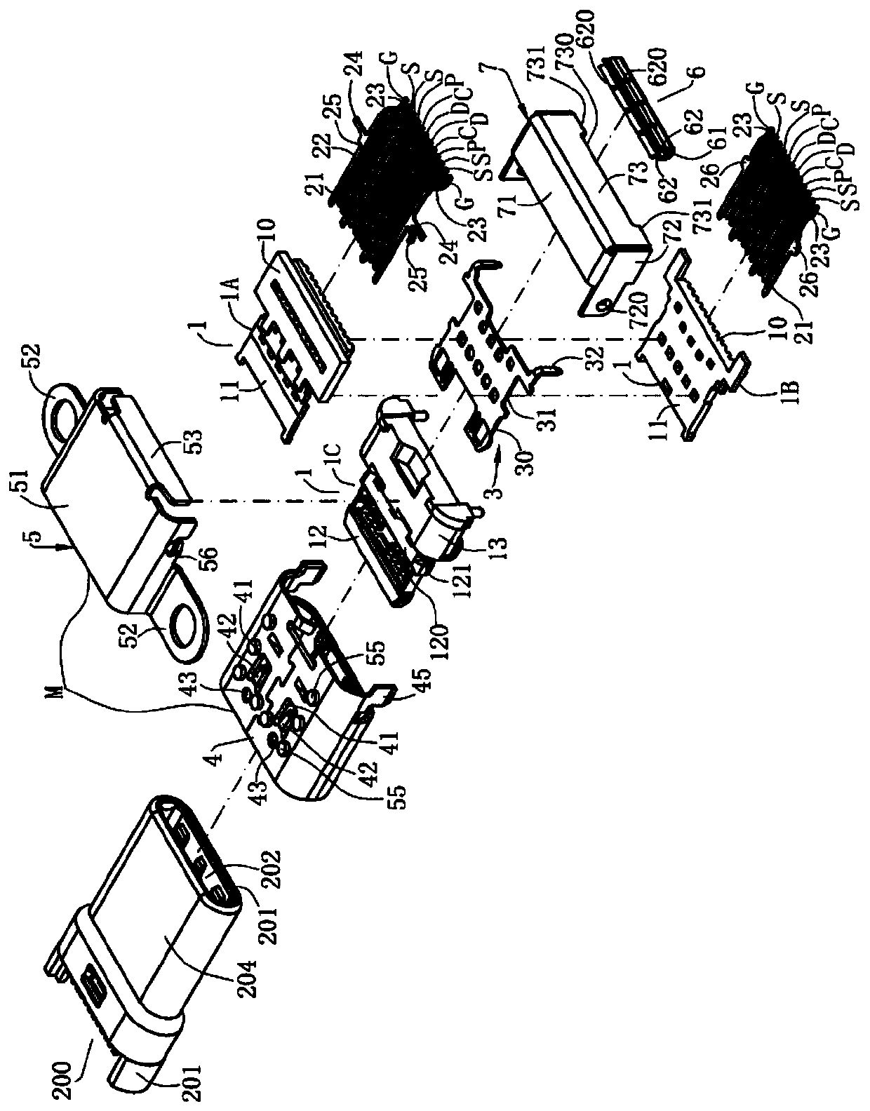
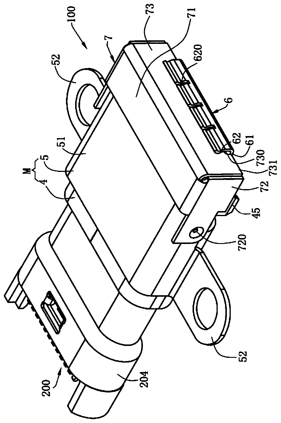
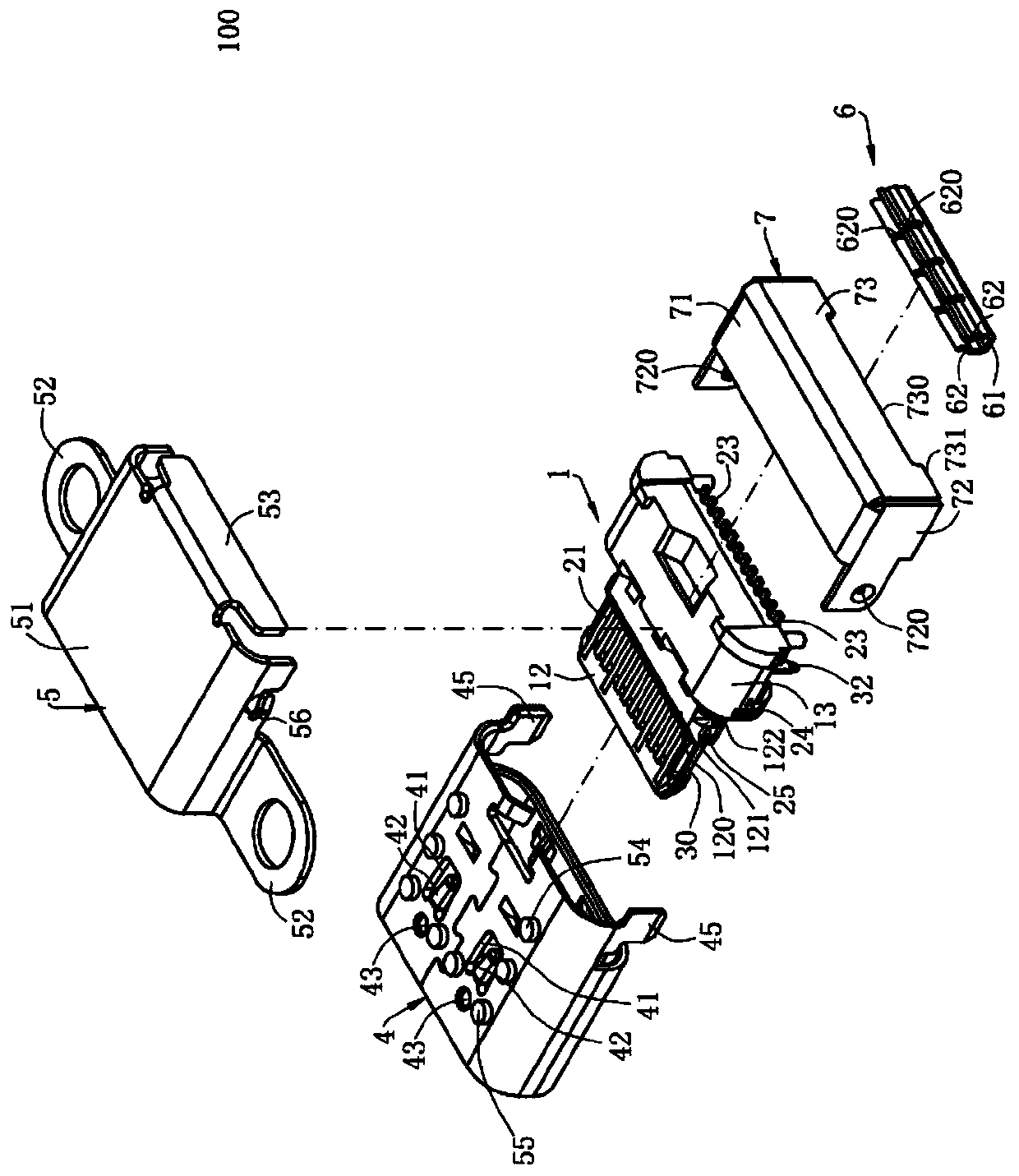
[0094] see figure 1 , figure 2 and image 3 , which is the first embodiment of the electrical connector 100 of the present invention. In this embodiment, the electrical connector 100 is a TYPE C type receptacle connector, which is installed on a circuit board 300 and docked with a plug connector 200. The plug connector 200 has a plastic body 201 , and the plastic body 201 has a receiving cavity 202 . The upper and lower rows of elastic contacts 203 are fixed in the plastic body 201 , exposed in the receiving cavity 202 , and in electrical contact with the electrical connector 100 . A ground piece (not shown) is fixed on the plastic body 201 and is located between the upper and lower rows of the elastic contacts 203, and th...


PUM


Abstract

The present invention discloses an electric connector, which is docked with a butting connector and installed on a circuit board. The electric connector comprises: a plurality of terminals fixed to aninsulating body, the terminal has a contact part and a conduction part located behind the contact part; the contact part electrically contacts with the butting connector and the conduction part extends out of the insulating body and electrically contacts with the circuit board; a grounding shell covering on the outside of the insulating body; and a shielding shell rotating relative to the insulating body between a closed position and an open position. A first end of the shielding shell is electrically conductive to the grounding shell. When the shielding shell is at the closed position, a second end of the shielding shell is electrically connected with at least one grounding medium; the grounding medium is installed on and electrically connected to the circuit board; when the shielding shell is at in the open position, an observation window is formed between the shielding shell and the grounding medium; the conduction part is exposed in the observation window to reduce the grounding path of the shielding shell; and high-frequency signal transmission is facilitated simultaneously.

Description

[0001] 【Technical field】 [0002] The invention relates to an electrical connector, in particular to an electrical connector which improves the transmission effect of high-frequency signals. [0003] 【Background technique】 [0004] A conventional electrical connector has an insulating body, a plurality of terminals are disposed on the insulating body, and the terminals have a welding portion extending out of the insulating body for welding with a circuit board, and a shielding shell covers the insulating body and is welded to the circuit plate, the welding part extends backward from the shielding shell and the insulating body, and the front end of an auxiliary shielding cover is movably installed on the rear end of the shielding shell, and the auxiliary shielding cover can slide in the front direction relative to the shielding shell so that A first position and a second position are formed, and the auxiliary shielding cover can slide backward from the first position to the seco...

Claims


Application Information

Patent Timeline
Patent Type & Authority Applications(China)
IPC IPC(8): H01R13/6581H01R13/6594
CPCH01R13/6581H01R13/6594H01R13/6595H01R24/64H01R2107/00H01R12/716H01R13/6587H01R24/66H01R13/641H01R13/6593H01R13/6582H01R12/722H01R12/775H01R12/88H01R13/658H01R12/724H01R13/6485H01R24/78H01R13/6583
Inventor 何东明金左锋
Owner DEYI PRECISION ELECTRONIC IND CO LTD PANYU
Learn More