

Servo welding head assembly
A technology of welding heads and components, applied in welding equipment, auxiliary welding equipment, welding/cutting auxiliary equipment, etc., can solve the problems of poor economic benefits and low efficiency, and achieve the effect of reasonable structure and guaranteed welding effect
- Summary
- Abstract
- Description
- Claims
- Application Information
AI Technical Summary
Problems solved by technology
Method used
Image

Examples
Embodiment Construction
[0020] Specific embodiments of the present invention will be described in detail below in conjunction with the accompanying drawings.
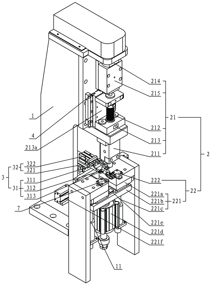
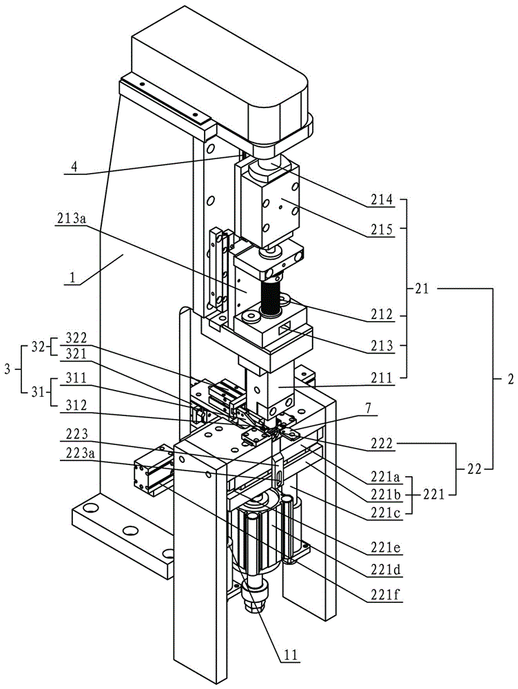
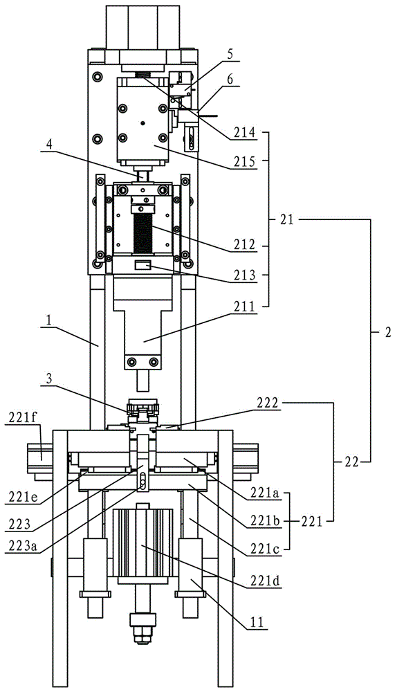
[0021] Such as figure 1 , 2 , 3, and 4 show a specific embodiment of the servo welding head assembly of the present invention. This embodiment comprises frame 1, spot welding mechanism 2 and positioning mechanism 3, and spot welding mechanism 2 and positioning mechanism 3 are arranged on the frame 1, and spot welding mechanism 2 comprises upper welding head group 21 and lower welding head group 22, upper The welding head group 21 is driven up and down by a servo motor. The lower welding head group 22 includes a lower bracket 221 that can move up and down and a lower welding head 222 that can move left and right and is arranged on both sides of the lower bracket 221. The positioning mechanism 3 is located on the upper welding head group. 21 and the lower welding head group 22, the positioning mechanism 3 includes a positioning claw 31 and a f...
PUM
 Abstract
Description
Claims
Application Information