Injection mold achieving in-mold automatic blanking

An injection mold and automatic technology, applied in the field of injection mold, can solve the problem of low efficiency of automatic material cutting, achieve the effect of simple structure, unaffected appearance and function, and reduce processing cost

Pending Publication Date: 2019-08-30
英力电子科技(重庆)有限公司
View PDF1 Cites 4 Cited by
  • Summary
  • Abstract
  • Description
  • Claims
  • Application Information

AI Technical Summary

Problems solved by technology

[0005] In order to solve the above problems, the present invention provides an injection mold with automatic material cutting in the mold, which solves the problem of low efficiency of automatic material cutting in the mold, realizes the rapid removal of the material port by the thimble, and improves the molding efficiency of injection molding

Method used


Image

  • Injection mold achieving in-mold automatic blanking
  • Injection mold achieving in-mold automatic blanking
  • Injection mold achieving in-mold automatic blanking

Examples


Embodiment 1

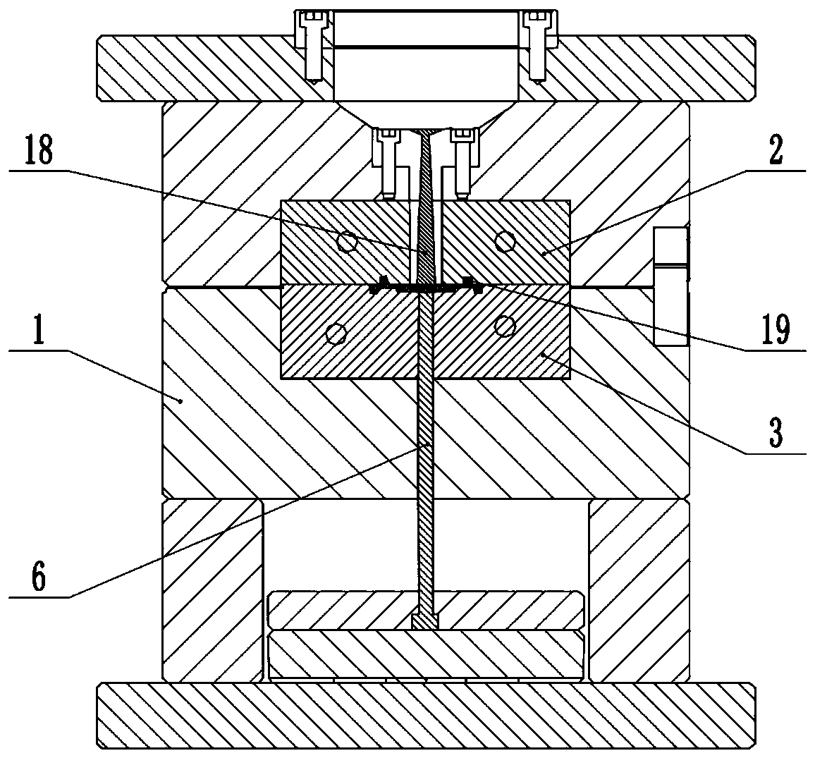
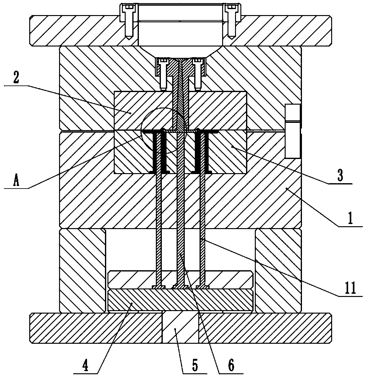
[0040] Example one is basically figure 2 , image 3 with Figure 4 As shown, an injection mold with automatic material cutting in the mold is provided with an ejection mechanism on the mold base 1. The ejection mechanism includes a push plate 4 vertically slidably connected to the mold base 1 and fixedly connected to the push plate 4 by screws. On the bottom driving ejector rod 5, the top of the push plate 4 is fixedly connected with a first ejector push rod 6 for demolding by screws.

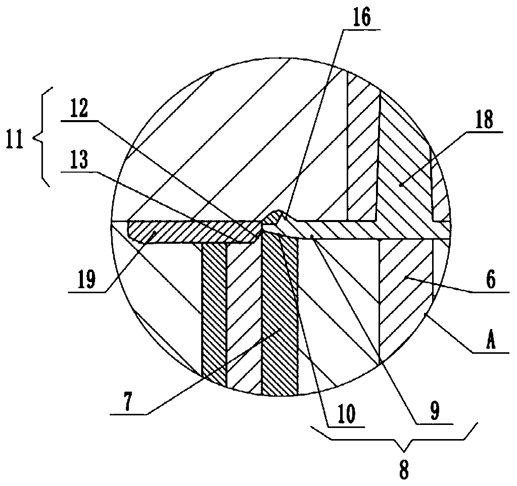
[0041] Combine figure 2 with image 3 , The movable mold 3 is provided with a vertical matching hole, and a tunnel-type pouring sub 7 is coaxially arranged in the matching hole. The bottom end of the tunnel-type pouring sub 7 is fixedly connected to the movable mold 3 by screws. The upper end of the type pouring sub 7 passes through the parting surface of the movable mold 3 and the fixed mold 2 and then extends into the fixed mold 2. Therefore, correspondingly, the fixed mold 2 is provided with a...

Embodiment 2

[0054] The difference between the second embodiment and the first embodiment is: Figure 5 As shown, if the volume of the product 19 is large, so that the mating part 13 cannot easily demold the product 19, the second ejection push rod 17 can be fixedly connected to the push plate 4 by screws at this time, and the second ejection push rod The top of 17 matches the shape of the bottom surface of the cavity. During demolding, the second ejector pin 17 can push the product 19 upwards out of the movable mold 3, so that the demolding is completed smoothly.


PUM


Abstract

The invention relates to the technical field of injection molds, in particular to an injection mold achieving in-mold automatic blanking. The injection mold comprises a fixed mold, a movable mold andan ejection mechanism which is arranged on the movable mold and used for ejecting products and a port. The movable mold is fixedly connected with a tunnel type pouring-in insert core, and a tunnel type pouring-in sprue channel is formed in the tunnel type pouring-in insert core. When the fixed mold and the movable mold are closed, the tunnel type pouring-in sprue channel and the tunnel type pouring-in insert core coincide. A chute penetrating through the tunnel type pouring-in sprue channel is formed in the tunnel type pouring-in insert core. The ejection mechanism is connected with a tool edge thimble, and the tool edge thimble is slidingly connected in the chute. When the injection mold is knocked out, the products and the port are demolded through the ejection mechanism, the ejection mechanism synchronously drives the tool edge thimble to automatically complete in-mold automatic cutting operation, and the port is fast cut out; the problem that in the prior art, the in-mold automaticcutting efficiency is low is solved; and the injection mold is simple in structure, can be easily improved on an existing injection mold, and is low in introduction cost.

Description

Technical field [0001] The invention relates to the technical field of injection molds, in particular to an injection mold with automatic material cutting in the mold. Background technique [0002] Injection mold is a tool for producing plastic products, and it is also a tool that gives plastic products a complete structure and precise dimensions. Injection mold is an important component of injection mold. Injection mold is the abbreviation of mold used for plastic injection molding. It is the realization of injection molding process. The important process equipment. The injection mold production process generally includes pre-molding preparation, injection process and product post-processing. Among them, the rubber material is poured into the cavity from the runner, and then cooled in the cavity to form the product, and the product is injected into the runner. The rubber material cools to form a spout. Due to the existing side gates and overlapped glue, the product and the spou...

Claims


Application Information

Patent Timeline
Patent Type & Authority Applications(China)
IPC IPC(8): B29C45/38B29C45/27B29C45/40
CPCB29C45/2708B29C45/38B29C45/401
Inventor 钟超利
Owner 英力电子科技(重庆)有限公司
Why Eureka
Try Eureka