Impedancd relay protection device according to phase compensation and method thereof

A technology for relay protection and impedance compensation, applied to emergency protection circuit devices, electrical components, etc., can solve problems such as reducing reliability and reducing operating speed

Inactive Publication Date: 2004-03-24
BEIJING SIFANG JIBAO AUTOMATION +1
View PDF0 Cites 7 Cited by
  • Summary
  • Abstract
  • Description
  • Claims
  • Application Information

AI Technical Summary

Problems solved by technology

Since the reliability of the option processing has not reached a satisfactory level, after the calculation and processing of the two components, the reliability is virtually reduced, and the action speed is also reduced

Method used


Image

  • Impedancd relay protection device according to phase compensation and method thereof
  • Impedancd relay protection device according to phase compensation and method thereof
  • Impedancd relay protection device according to phase compensation and method thereof

Examples


Embodiment Construction

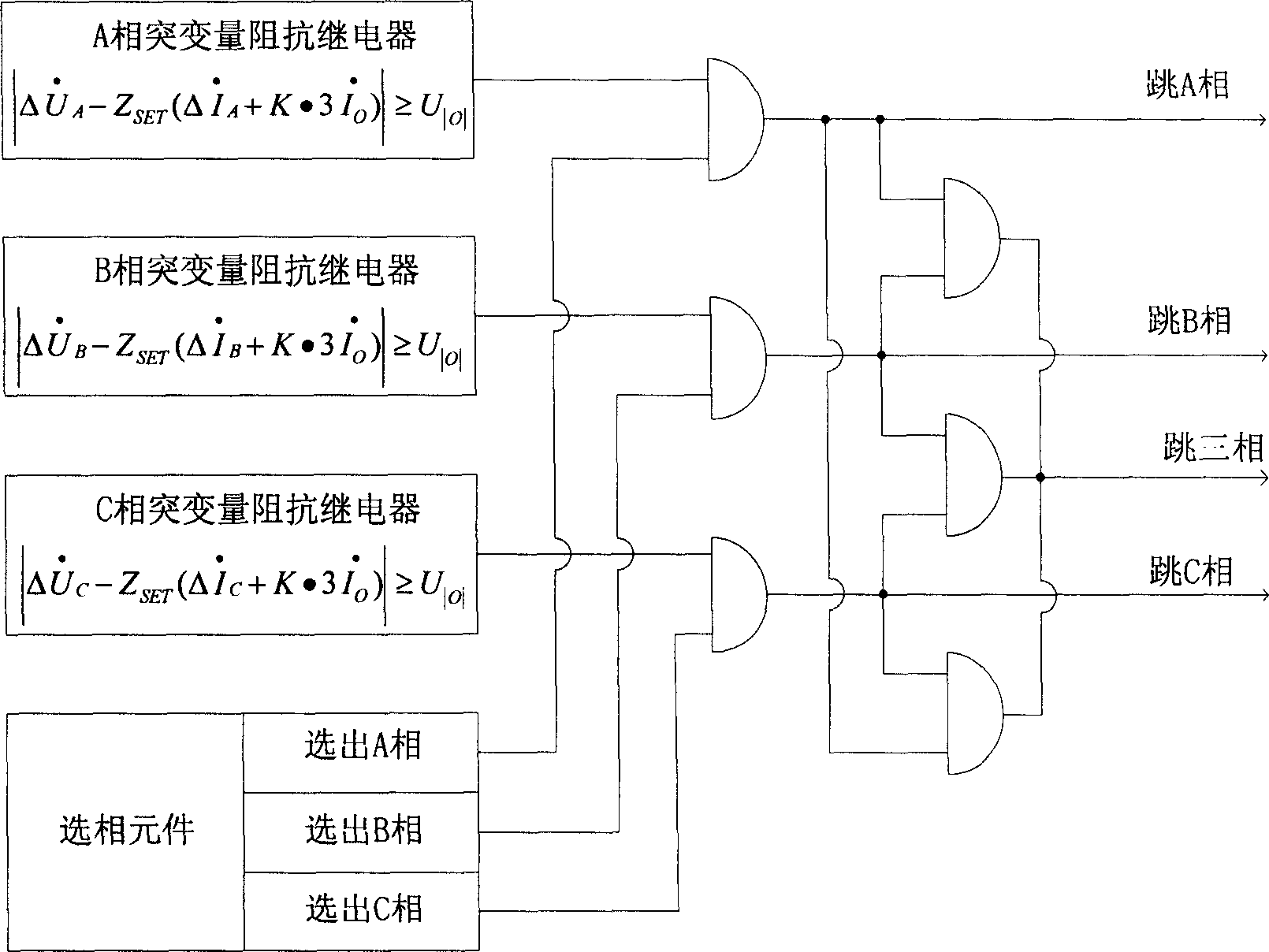
[0054] figure 1 It is a schematic diagram of the logic principle of the abrupt change impedance relay protection device. Such as figure 1 As shown, in the existing sudden change impedance relay protection device, the signal output from the sudden change impedance relay must go through the "AND gate" twice with the signal output by the phase selection element, and then the phase jump device will act, as in the background According to the technical analysis of the phase compensation impedance relay protection device, since the reliability of the option processing has not yet reached a satisfactory level, after the calculation and processing of the two components, the reliability is virtually reduced, and at the same time Reduced movement speed.

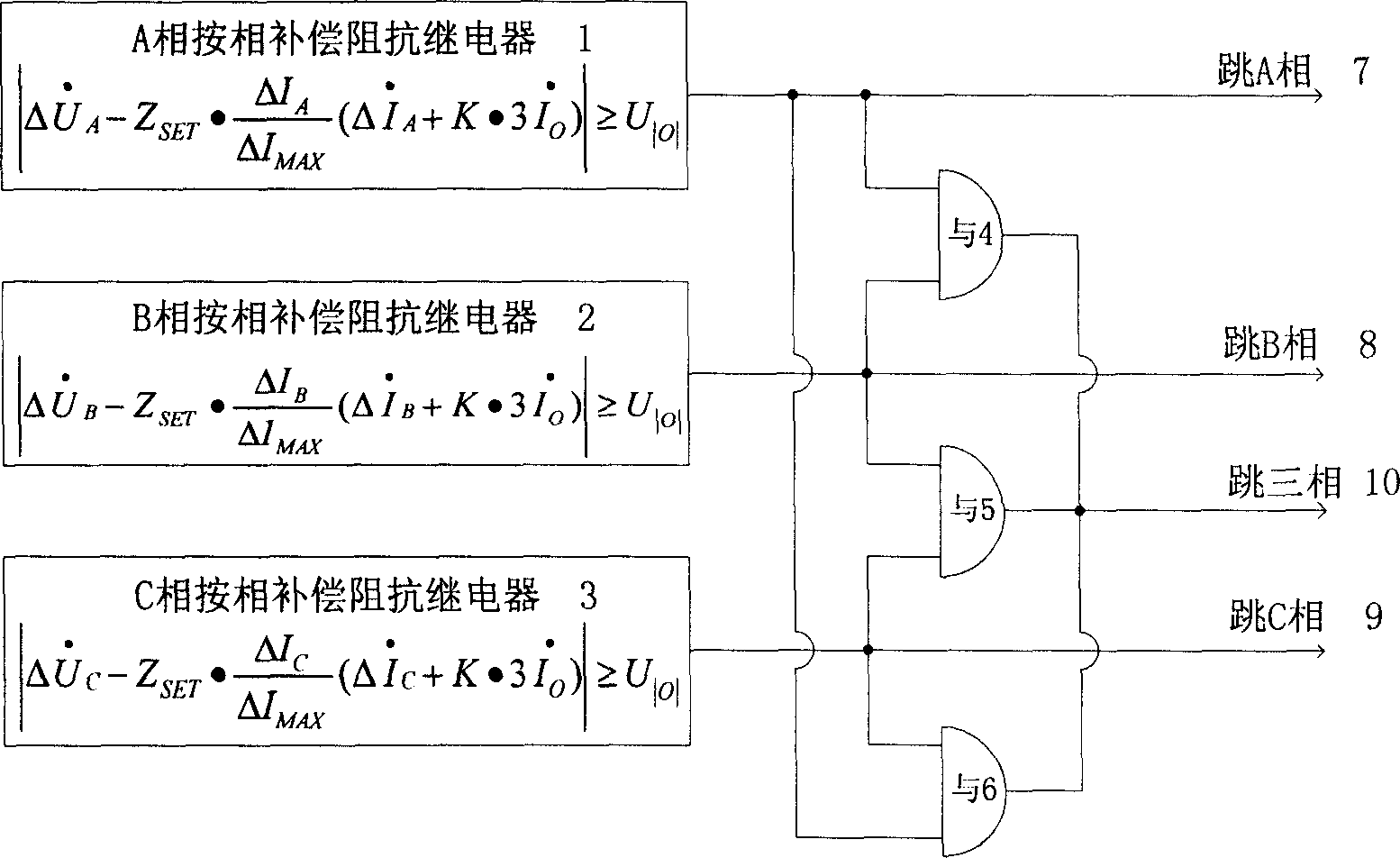
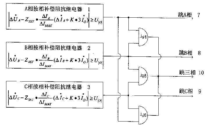
[0055] figure 2 It is a schematic diagram of the logic principle of the phase compensation impedance relay protection device. Such as figure 2 As shown, the described a phase compensation impedance relay protection device include...


PUM


Abstract

This invention discloses a protection device of a phase compensation impedance relay including: A,B and C are compensated in terms of phase separately to make up of a phase compensation impedance relay connecting to jump A, jump B, jump C by transmission lines and connecting to a three phase jump device by AND gate for detecting transmission line phase A,B, C performance and state, if one phase faults, then only one phase jump is realized, if two or three phases fault, then three phase jumps are realized.

Description

technical field [0001] The invention relates to a power system and an automatic device thereof, in particular to a relay protection device and method. technical background [0002] In the power system and its automation system, when the transmission line fails, the faulty line needs to be cut off as soon as possible by the relay protection equipment. Impedance (distance) relay device is the most commonly used equipment for relay protection. [0003] The sudden change impedance (distance) relay is a relay with better performance in relay protection, and the action equation of the sudden change impedance (distance) relay is: [0004] | Δ U · φ - Z SET ( Δ I · φ + K · 3 ...

Claims


Application Information

Patent Timeline
Patent Type & Authority Applications(China)
IPC IPC(8): H02H7/26
Inventor 黄少锋陶惠良张月品杜兆强张效宇
Owner BEIJING SIFANG JIBAO AUTOMATION
Why Eureka
Try Eureka