Thermal transfer ribbon installation structure for thermal transfer printer

A technology of thermal transfer printer and installation mechanism, which is applied in the direction of printing and inking devices, and can solve the problems of complex installation or removal of carbon ribbons and the need for empty paper reels, etc.

Active Publication Date: 2019-08-30
DELI GROUP CO LTD
View PDF9 Cites 2 Cited by
  • Summary
  • Abstract
  • Description
  • Claims
  • Application Information

AI Technical Summary

Problems solved by technology

[0003] The technical problem to be solved by the present invention is to provide a method that avoids the complicated installation or removal of the current carbon ribbon and requires an empty paper reel; when installing, only the glued side of the carbon ribbon needs to be glued to the self-contained reel , or wind the carbon ribbon on the shaft two or three times, then install it, and take it off by loosening the carbon ribbon. When it is down, it shrinks inward, which makes the installation more convenient. Thermal transfer printer ribbon installation mechanism

Method used


Image

  • Thermal transfer ribbon installation structure for thermal transfer printer
  • Thermal transfer ribbon installation structure for thermal transfer printer
  • Thermal transfer ribbon installation structure for thermal transfer printer

Examples


Embodiment Construction

[0029] The present invention will be further described below in conjunction with accompanying drawing.

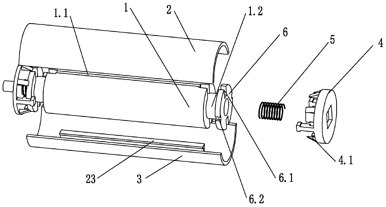
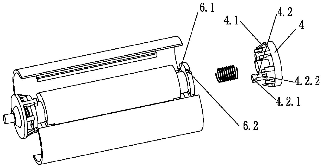
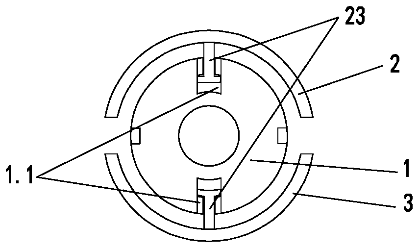
[0030] Such as Figure 1-6 As shown, the carbon ribbon installation mechanism of the thermal transfer printer of the present invention includes a main shaft 1 and a casing for installing the carbon ribbon and is located outside the main shaft 1, and is characterized in that the casing includes at least two pieces divided radially The formed shells have spacing between the side walls of adjacent shells, and each shell is limited in the circumferential direction with the main shaft 1 and slides in the radial direction. The two ends of the main shaft 1 are connected with brackets 4, and the brackets at one end The outer end of 4 is a rectangular hole, the outer end of the bracket 4 at the other end is a cylindrical protrusion, and the other structures are the same. The bracket 4 slides along the axial direction of the main shaft 1 and a spring 5 is arranged on the bracket 4 a...


PUM


Abstract

The invention discloses a thermal transfer ribbon installation structure for a thermal transfer printer. The thermal transfer ribbon installation structure comprises a spindle (1) and a shell used forinstalling a thermal transfer ribbon and located outside the spindle (1). The shell at least comprises two shell pieces formed by cutting in the radial direction, a gap is arranged between the side walls of every two adjacent shell pieces, and each shell piece is in circumferential limit with the spindle (1) and slides in the radial direction. The two ends of the spindle (1) are connected with brackets (4), the brackets (4) slide in the axial direction of the spindle (1), and springs (5) are arranged on the brackets (4) and the spindle (1). When the thermal transfer ribbon is installed in theprinter, the brackets (4) on both sides slide toward the center along the spindle (1), when the thermal transfer ribbon is taken out of the printer, the brackets (4) on both sides slide to two ends along the spindle (1) under the action of the springs, the shell contracts radially under the action of external force, and the shell pieces are presented with multiple segments of circular arcs. The main movement of the printer is to realize outward expansion of a plastic part on the outermost ring during installation and inward contraction during taking down, and installation is more convenient.

Description

technical field [0001] The invention relates to the technical field of thermal transfer printers, in particular to a carbon ribbon installation mechanism for thermal transfer printers. Background technique [0002] The current carbon ribbon printer has the following forms in the process of installing the carbon ribbon: 1. With a detachable plastic shaft, the plastic shaft is removed when in use, the empty paper reel is set on the plastic shaft, and then installed on the printer , just take off the entire empty paper reel when recycling. This form is widely used in thermal transfer printers, but this form must use an empty paper reel, the longer carbon ribbon is purchased without this paper reel, and this method will make it unusable if the empty paper reel is lost in hand; And this installation form is relatively complicated, and it cannot be installed normally for the first time. 2. There is an aluminum shaft directly. This form of carbon ribbon installation does not need...

Claims


Application Information

Patent Timeline
Patent Type & Authority Applications(China)
IPC IPC(8): B41J33/00
CPCB41J33/003
Inventor 曹硕
Owner DELI GROUP CO LTD
Why Eureka
Try Eureka