
Brush roller and scrubber provided with brush roller

A brush roller and brush technology, which is applied in carpet cleaning, cleaning machinery, floor cleaning, etc., can solve the problems of multiple disassembly and assembly steps of roller brushes, poor user experience, inconsistent resistance of brush rollers, etc.

Pending Publication Date: 2022-06-28
WUHAN DIISEA INTLLIGENCE TECH CO LTD
View PDF8 Cites 2 Cited by
  • Summary
  • Abstract
  • Description
  • Claims
  • Application Information

AI Technical Summary

Problems solved by technology

[0004] The roller brush assembly in the existing air dust circulation floor cleaner all adopts a more complicated way to fix one end, and the other end is driven by a separate gear set or synchronous belt. The drive motor provides the driving force. When the roller brush needs to be maintained separately, there are many steps to disassemble and assemble the roller brush, and the user experience is not good.
[0005] At present, the roller brush assembly in the water and dust circulation floor cleaner adopts a relatively complicated way to fix one end, and the other end is driven by a separate drive motor through a gear set Or directly driven by the built-in deceleration device of the motor, when the roller brush needs to be maintained separately, there are many steps to disassemble and assemble the roller brush, and the user experience is not good
Moreover, disassembling and assembling the brush cylinder by repeatedly disassembling and assembling the fastening screw at the non-drive end will cause inconsistent resistance to one end of the brush cylinder

Method used


Image

  • Brush roller and scrubber provided with brush roller
  • Brush roller and scrubber provided with brush roller
  • Brush roller and scrubber provided with brush roller

Examples


Embodiment Construction

[0048] The claims of the present invention will be further described in detail below with reference to the specific embodiments and the accompanying drawings. Obviously, the described embodiments are only a part of the embodiments of the present invention, rather than all the embodiments. Based on the embodiments of the present invention, all other embodiments obtained by those of ordinary skill in the art without creative work, also belong to the protection scope of the present invention.

[0049] It should be understood that, in the description of the embodiments of the present invention, all directional indicated terms, such as "up", "down", "left", "right", "front", "rear", etc. indicate the orientation or position The relationship is based on the orientation and positional relationship shown in the drawings or the orientation or positional relationship that the product of the invention is usually placed in use, and is only for the convenience of simplifying the description...


PUM


Abstract

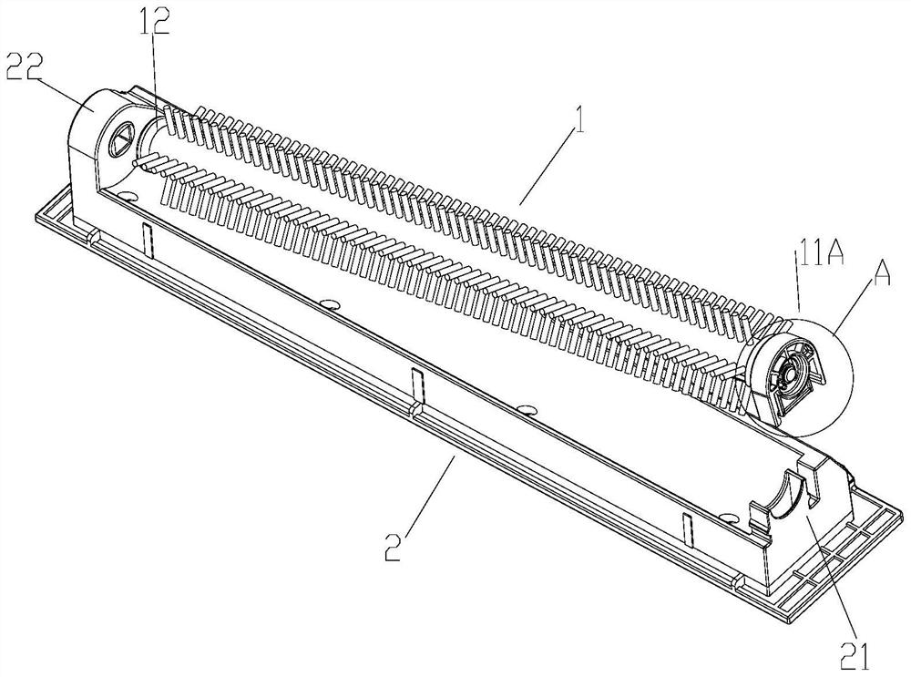
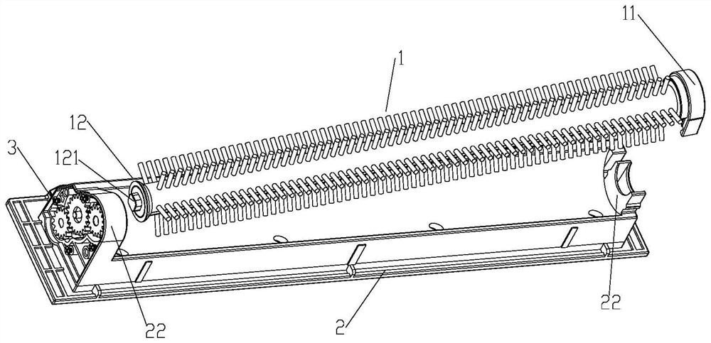
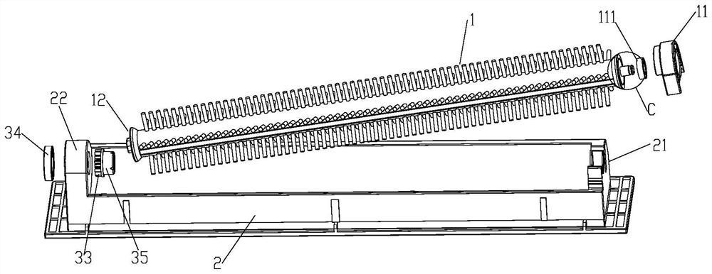
The invention discloses a brush roller and a scrubber provided with the brush roller. The brush roller comprises a brush roller body and a fixing mechanism used for installing the brush roller body. The fixing mechanism is respectively provided with a first matching part matched and fixed with the first end of the brush roller body and a second matching part matched and fixed with the second end of the brush roller body, the first end of the brush roller body is provided with a bearing, and the bearing is fixed with the brush handle; the first matching part is provided with a fixing clamping structure used for fixing a brush handle, the second end of the brush roller body is provided with a transmission gear and a rotating shaft coaxially extending along the transmission gear, the end face of the rotating shaft is provided with a cavity for containing a protruding block arranged at the second end of the brush roller body, and the wall of the cavity is a non-cylindrical face. Due to the fact that the matching mode of the non-driving end of the brush roller and the corresponding support of the brush roller assembly shell is changed, the brush roller can be conveniently taken out with one hand, and the service life can be prolonged.

Description

technical field [0001] The invention relates to the technical field of cleaning equipment, in particular to a brush roller and a washing machine equipped with the brush roller. Background technique [0002] The brush roller configured in the washing machine with water-dust circulation technology is installed in the cleaning head to sweep the garbage lifted up by the sponge roller to the garbage box. The brush roller does not need to sweep the ground, but only needs to be closed The lower and rear section of the cleaning space sweeps the surface of the sponge drum after being washed by clean water in the closed cleaning space, and sweeps the garbage that is blocked by the filter device of the closed cleaning space outside the water flow channel to the garbage box. [0003] Chinese patent document CN112674642A discloses a rolling brush assembly, comprising a first rolling brush, a reciprocating mechanism and a cutting member; the cutting member is connected with the reciprocat...

Claims


Application Information

Patent Timeline
Patent Type & Authority Applications(China)
IPC IPC(8): A47L11/40A47L11/282
CPCA47L11/4041A47L11/4069A47L11/40A47L11/282
Inventor 周杰万科学
Owner WUHAN DIISEA INTLLIGENCE TECH CO LTD
Learn More