High-rise building rescue equipment based on unmanned aerial vehicle technology

A high-rise building and unmanned aerial vehicle technology, applied in the field of high-rise building rescue equipment based on unmanned aerial vehicle technology, can solve the problems of inaccessibility, instability and height of fire fighting equipment.

Inactive Publication Date: 2019-08-30
河南大域航空科技有限公司
View PDF7 Cites 2 Cited by
  • Summary
  • Abstract
  • Description
  • Claims
  • Application Information

AI Technical Summary

Problems solved by technology

At present, fire rescue and fire fighting in high-rise buildings is one of the three major problems recognized in the world. Due to the high floor height, most of the fire-fighting equipment is difficult to reach at present, and the pressure of fire-fighting hydrants is not enough, etc., and helicopter rescue is difficult to approach due to the complexity of the fire scene.
[0003] Therefore, a high-rise fire-fighting and rescue flight cabin is disclosed in the patent literature with the publication number CN205113740U, which includes a cabin body, a hatch, a multi-axis flight mechanism, etc. The cabin can be raised to the emergency floor through the control of the rescuers for rescue and fire fighting. Compared with the traditional ladder rescue, the rescue cabin can adapt to higher floors. However, when the flight cabin is in use, it needs to be suspended in the air. For a period of time, the internal fire extinguishing treatment will be carried out. During this period of time, it will be impacted by the heat wave. Since there is no supporting mechanism, it will be pushed away and will be extremely unstable in the air. At the same time, when entering the building for rescue, the cabin will The landing is only supported by the fixed support frames on both sides. After being impacted, there is a hidden danger of tipping

Method used


Image

  • High-rise building rescue equipment based on unmanned aerial vehicle technology
  • High-rise building rescue equipment based on unmanned aerial vehicle technology
  • High-rise building rescue equipment based on unmanned aerial vehicle technology

Examples


Embodiment Construction

[0020] The following will clearly and completely describe the technical solutions in the embodiments of the present invention with reference to the accompanying drawings in the embodiments of the present invention. Obviously, the described embodiments are only some, not all, embodiments of the present invention. Based on the embodiments of the present invention, all other embodiments obtained by persons of ordinary skill in the art without making creative efforts belong to the protection scope of the present invention.

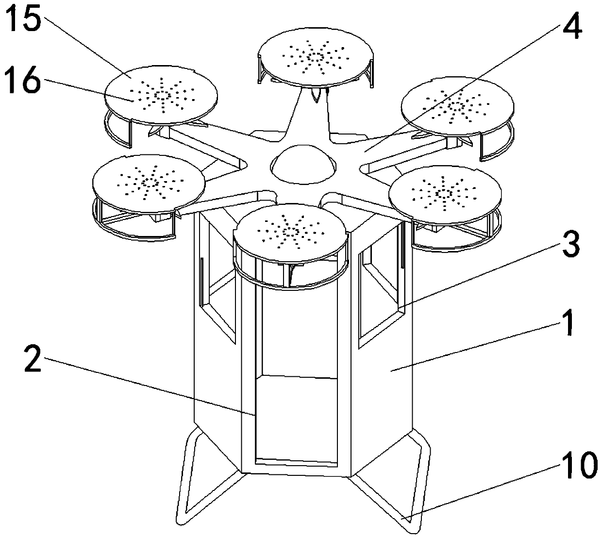
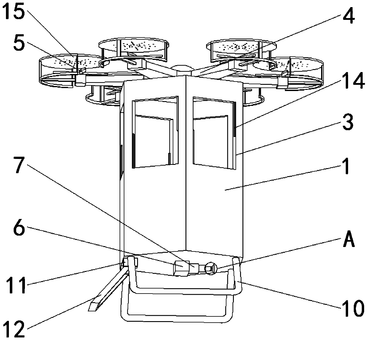
[0021] see Figure 1-4 , including cabin body 1, hatch door 2, window 3, connector 4 and multi-axis flying mechanism 5, the cabin body is hexagonal, the number of windows 3 is five, the number of multi-axis flying mechanism 5 is six, five A window 3 and a hatch 2 are respectively located on the side of the cabin body 1, a connector 4 is rotatably installed on the top of the cabin body 1, six multi-axis flight mechanisms 5 are rotatably installed on the connect...


PUM


Abstract

The invention relates to the technical field of high-rise building rescue equipment, and discloses high-rise building rescue equipment based on an unmanned aerial vehicle technology. The high-rise building rescue equipment comprises a cabin body, a cabin door, windows, a connector and multi-axis flying mechanisms, wherein the number of the windows is five, the number of the multi-axis flying mechanisms is six, the five windows and the cabin door are correspondingly located on the side surfaces of the cabin body, the connector is rotationally installed at the top of the cabin body, the six multi-axis flying mechanisms are rotationally installed on the connector, the bottom of the cabin body is fixedly provided with a connecting block, and the front side of the connecting block is rotationally provided with a multi-stage telescopic cylinder. According to the high-rise building rescue equipment based on the unmanned aerial vehicle technology, after a sucking plate is fixed to a glass on the bottom layer, the sucking plate can be connected to the cabin body through the multi-stage telescopic cylinder, so that when the fire is treated, the multi-stage telescopic cylinder can limit the movement of the cabin body, and the cabin body can be prevented from being pushed too far under the impact of heat waves.

Description

technical field [0001] The invention relates to the technical field of high-rise building rescue equipment, in particular to a high-rise building rescue equipment based on unmanned aerial vehicle technology. Background technique [0002] Article 1.0.2 of my country's "Technical Regulations for Concrete Structures of High-rise Buildings" (JGJ 3-2010) stipulates that residential buildings with 10 floors and above or with a building height greater than 28m and other high-rise civil buildings with a building height greater than 24m are high-rise buildings. . At present, fire rescue and fire fighting in high-rise buildings is one of the three major problems recognized in the world. Due to the high floor height, most of the fire-fighting equipment is difficult to reach at present, and the pressure of fire-fighting hydrants is not enough, etc., and helicopter rescue is difficult to approach due to the complexity of the fire scene. . [0003] Therefore, a high-level fire-fighting a...

Claims


Application Information

Patent Timeline
Patent Type & Authority Applications(China)
IPC IPC(8): B64C27/08B64C25/32B64C25/62B64D47/00
CPCB64C27/08B64C25/32B64C25/62B64D47/00B64U10/10B64U2101/00
Inventor 姚东辉石为宇
Owner 河南大域航空科技有限公司
Why Eureka
Try Eureka