
A Double Wall Cooling Structure for Jet Engine Vectoring Nozzle

A technology of jet engine and vector nozzle, applied in the direction of machine/engine, jet propulsion device, etc., can solve the problems of increasing impact distance and uneven thermal stress of corrugated heat shield

Inactive Publication Date: 2021-09-10
NORTHWESTERN POLYTECHNICAL UNIV +1
View PDF7 Cites 0 Cited by
  • Summary
  • Abstract
  • Description
  • Claims
  • Application Information

AI Technical Summary

Problems solved by technology

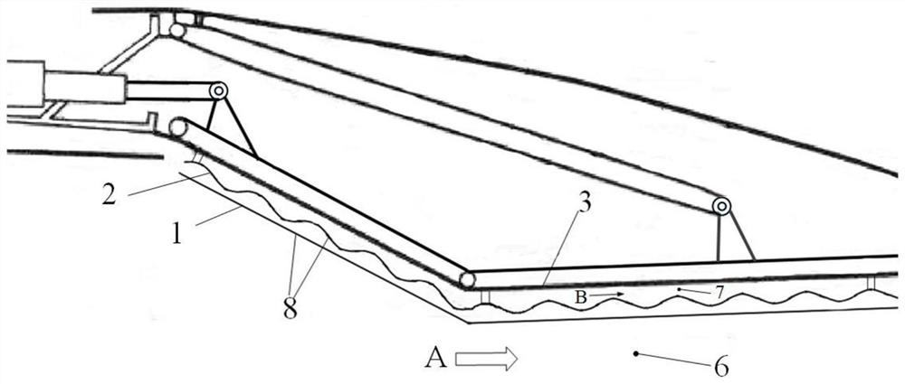
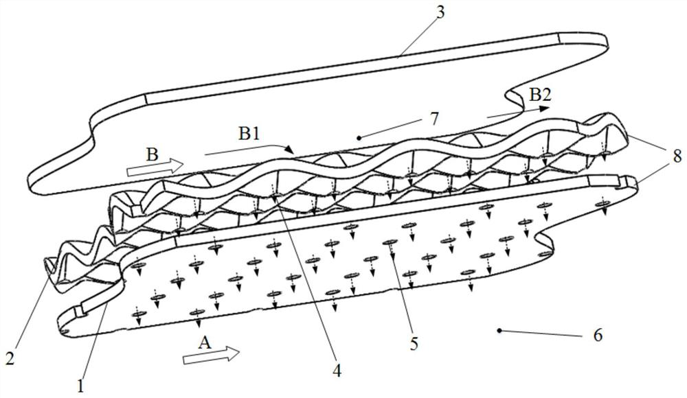
[0004] The technical problem solved by the present invention is: in order to solve the contradiction between the need to enhance the heat transfer and reduce the impact distance in the prior art, but to reduce the flow resistance and increase the impact distance, and solve the problem of corrugated heat insulation at the same time The problem of uneven heat shield stress, the present invention relates to a double wall cooling structure for jet engine vectoring nozzle

Method used


Image

  • A Double Wall Cooling Structure for Jet Engine Vectoring Nozzle
  • A Double Wall Cooling Structure for Jet Engine Vectoring Nozzle
  • A Double Wall Cooling Structure for Jet Engine Vectoring Nozzle

Examples


Embodiment 1

[0049] Embodiment one: impact hole diameter d c is 1mm, and the diameter of the gas film hole is d f is 1mm, and the impact distance h is 3d c , the distance between the impact holes along the gas flow direction P c1 10mm, spanwise spacing of impact holes P c2 is 5mm, and the distance between gas film holes along the gas flow direction is P f1 is 10mm, the spanwise spacing of gas film holes P f2 is 5mm. The impact plate is divided into two types, one is the impact corrugated plate amplitude A c 0.2mm, and the other is the impact plate, that is, the traditional impact plate. Impact plate and air film plate thickness δ c , f Both are 1mm, the angle θ formed by the impact hole and the gas film hole and the gas flow direction c , θ f Both are 90°, and Re is 1700.

Embodiment 2

[0050] Embodiment two: impact hole diameter d c is 1mm, and the diameter of the gas film hole is d f is 1mm, and the impact distance h is 3d c , the distance between the impact holes along the gas flow direction P c1 10mm, spanwise spacing of impact holes P c2 is 5mm, and the distance between gas film holes along the gas flow direction is P f1 is 10mm, the spanwise spacing of gas film holes P f2 is 5mm. The impact plate is divided into two types, one is the impact corrugated plate amplitude A c 0.5mm, and the other is the impact plate, that is, the traditional impact plate. Impact plate and air film plate thickness δ c , f Both are 1mm, the angle θ formed by the impact hole and the gas film hole and the gas flow direction c , θ f Both are 90°, and Re is 1700.

Embodiment 3

[0051] Embodiment three: impact hole diameter d c is 1mm, and the diameter of the gas film hole is d f is 1mm, and the impact distance h is 3d c , the distance between the impact holes along the gas flow direction P c1 10mm, spanwise spacing of impact holes P c2 is 5mm, and the distance between gas film holes along the gas flow direction f1 10mm, air film hole spanwise spacing P f2 is 5mm. The impact plate is divided into two types, one is the impact corrugated plate amplitude A c 0.8mm, the other is the impact plate, that is, the traditional impact plate. Impact plate and air film plate thickness δ c ,δ f Both are 1mm, the angle θ formed by the impact hole and the gas film hole and the gas flow direction c , θ f Both are 90°, and Re is 1700.

[0052] When analyzing the results, the Nusselt number Nu is used to measure the heat transfer effect, and the flow coefficient C is used. d A measure of pressure loss. as attached Figure 9 As shown, the horizontal axis is...


PUM


Abstract

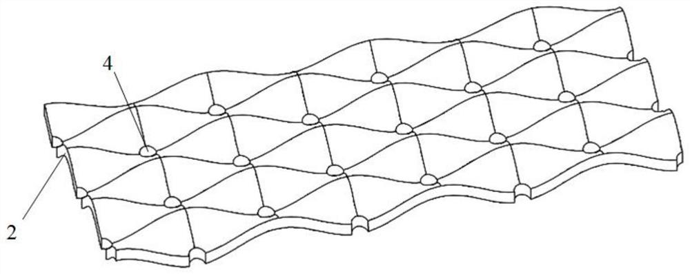
The invention relates to a double-wall cooling structure for a jet engine vector nozzle, which uses a three-dimensional corrugated impact plate and a flat air film plate to form a double-wall cooling structure. The impact holes and gas film holes are distributed in a "chessboard" pattern, that is, the impact holes are arranged at the troughs of the corrugated impact orifice plate, and the gas film holes on the gas film orifice plate are arranged at the crests of the corrugated impact orifice plate; The corrugated impact orifice plate and the gas film orifice plate have multiple unit periodic structures in the axial direction. A small impact distance is formed between the wave trough and the air film orifice plate, which can enhance the impact heat transfer, and a large space can be formed between the wave crest and the air film orifice plate, which is conducive to the full development of the cold air flow and the outflow, which can reduce the flow Improve the utilization rate of cold air, and solve the contradiction between reducing the impact distance in order to enhance heat transfer, but increasing the impact distance in order to reduce flow resistance. At the same time, the air film plate is a flat plate, which is conducive to the attachment of the air film, forming effective thermal protection and reducing thermal stress.

Description

technical field [0001] The invention belongs to the field of aero-engine vectoring nozzle cooling, and is also used for the cooling of engine combustion chambers and afterburner heat shields, in particular to a double-wall cooling structure for jet engine vectoring nozzles. Background technique [0002] The vector nozzle plays an important role in improving the maneuverability of the aircraft. The temperature of the gas in the nozzle can reach above 2000K. Let it cool. Since the cooling air of the nozzle is extracted from the compressor of the engine, this part of the cold air will not be able to participate in the entire thermal cycle of the engine, which will reduce the thermal efficiency and thrust of the engine. Therefore, when designing a high-performance nozzle, it is necessary to achieve as much as possible It is possible to achieve a higher cooling effect with less cold air. [0003] The double-wall cooling structure is an impingement / divergent cooling structure, w...

Claims


Application Information

Patent Timeline
Patent Type & Authority Patents(China)
IPC IPC(8): F02K1/82
CPCF02K1/822
Inventor 郭涛谢龙刘存良母鸿瑞罗红飞
Owner NORTHWESTERN POLYTECHNICAL UNIV
Learn More