
Refrigeration visualization device

A condenser and console technology, applied in the field of refrigeration visualization devices, can solve the problems of lack of intuitive understanding of the state of the refrigerant and the working process, the sealing of the evaporator, the condenser and the evaporator, and the observation of the refrigeration system by students. Intuitive teaching, stable structure, simple operation effect

Pending Publication Date: 2019-08-30
林鹿
View PDF0 Cites 1 Cited by
  • Summary
  • Abstract
  • Description
  • Claims
  • Application Information

AI Technical Summary

Problems solved by technology

However, in the current teaching experiment, various teaching experiment platforms, especially the refrigeration system teaching platform, cannot allow students to observe the working process of the refrigeration system intuitively, and students do not have an intuitive understanding of the state and working process of the refrigerant in the refrigeration system. Learning disabilities, especially since the evaporators, condensers, expansion valves, and evaporators in most experimental platforms are sealed and invisible

Method used


Image

  • Refrigeration visualization device
  • Refrigeration visualization device
  • Refrigeration visualization device

Examples


Embodiment Construction

[0019] The following will clearly and completely describe the technical solutions in the embodiments of the present invention with reference to the accompanying drawings in the embodiments of the present invention. Obviously, the described embodiments are only some, not all, embodiments of the present invention.

[0020] In describing the present invention, it should be understood that the terms "upper", "lower", "front", "rear", "left", "right", "top", "bottom", "inner", " The orientation or positional relationship indicated by "outside", etc. is based on the orientation or positional relationship shown in the drawings, and is only for the convenience of describing the present invention and simplifying the description, rather than indicating or implying that the referred device or element must have a specific orientation, so as to Specific orientation configurations and operations, therefore, are not to be construed as limitations on the invention.

[0021] refer to Figure ...


PUM


Abstract

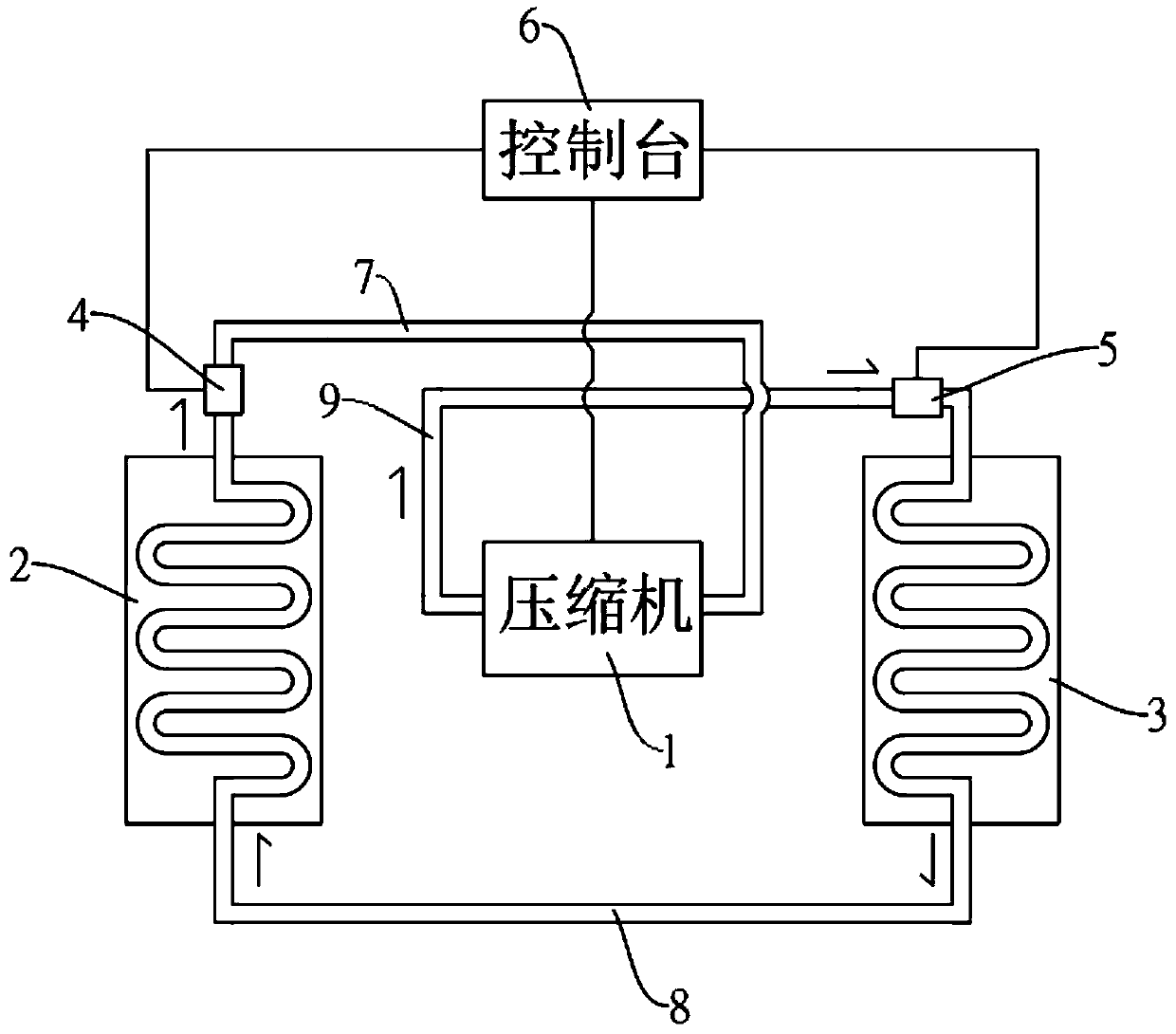
The invention discloses a refrigeration visualization device which comprises a compressor. The refrigeration visualization device is characterized in that the input end of the compressor communicateswith the output end of a visualization evaporator through a first connecting copper tube, and the output end of the compressor communicates with the input end of a visualization condenser through a third connecting copper tube; and the input end of the visualization evaporator communicates with the output end of the visualization condenser through a second connecting copper tube. The refrigerationvisualization device is stable in structure, simple in operation and scientific and reasonable in design. The visualization evaporator and the visualization condenser can be used for intuitively observing a running path and flow direction of two phases of gas and liquid, and intuitive teaching is convenient. A controller processes data collected by a pressure sensor and a temperature sensor, anda display device outputs the information collected by the pressure sensor and the temperature sensor, so that a lot of time and effort of an experimenter can be saved.

Description

technical field [0001] The invention relates to the technical field of refrigeration equipment, in particular to a refrigeration visualization device. Background technique [0002] In thermal energy and power engineering majors, colleges and universities have also set up refrigeration-related majors or increased investment in refrigeration majors. However, in the current teaching experiment, various teaching experiment platforms, especially the refrigeration system teaching platform, cannot allow students to observe the working process of the refrigeration system intuitively, and students do not have an intuitive understanding of the state and working process of the refrigerant in the refrigeration system. Learning disabilities, especially the evaporators, condensers, expansion valves, and evaporators in most experimental platforms are sealed and invisible. In this context, it is very important to visualize and transform the individual components of the refrigeration system...

Claims


Application Information

Patent Timeline
Patent Type & Authority Applications(China)
IPC IPC(8): G09B25/02
CPCG09B25/02
Inventor 林鹿林炳南邵建荣余霄骏
Owner 林鹿
Learn More